When racks climb from 50 to 200 kW, air alone hits a wall: heat flux at the die skyrockets, room delta‑T tightens, and fan energy soars. The practical path is modular liquid cooling—deployable in pods, rack by rack, with controls, safety, and KPI reporting aligned to recognized standards. This guide shows how to select the right approach, design and commission the loop, and retrofit brownfield rows with minimal downtime while targeting PUE ≤ 1.25 and near‑zero WUE.
Key takeaways
Single‑phase direct‑to‑chip with rack/row CDUs, plus RDHx for residual heat, is the most brownfield‑friendly route to 50–200 kW/rack with near‑zero WUE.
Engineer to standards: use ASHRAE W‑classes (e.g., W40–W45) for warm‑water operation and report PUE/WUE/ERF using ISO/IEC 30134 and EN 50600‑4 structures.
Safety is layered: L2L heat exchangers, dripless quick‑disconnects, multi‑zone leak detection, and fail‑safe shutoff near headers and racks.
Commission methodically: flush, purge, verify flows/pressures, tune controls, and run stepped thermal acceptance before production.
Retrofit in phases: add row manifolds and CDUs first, integrate liquid‑ready servers, then neutralize room heat with RDHx where needed.
A decision framework for modular liquid cooling
Choosing among direct‑to‑chip, two‑phase, immersion, and hybrid patterns depends on density, downtime tolerance, and water availability. Use this matrix to narrow the fit, then confirm with a thermal survey and CFD.
Constraint | 50–120 kW/rack | 120–200 kW/rack | Downtime tolerance | Facility water availability |
|---|---|---|---|---|
Preferred pattern | Single‑phase direct‑to‑chip + RDHx | Single‑phase direct‑to‑chip (tight envelopes) or two‑phase direct‑to‑chip; immersion for blocks | Brownfield: direct‑to‑chip + RDHx; Greenfield: any | Limited water: two‑phase direct‑to‑chip or immersion; Warm‑water capable: direct‑to‑chip W40–W45 |
Retrofit fit | High | Medium (verify manifolds and delta‑P) | High with staged cutovers | Medium–High if L2L isolation is used |
Water/energy outcomes | Near‑zero WUE; PUE ≤ 1.25 achievable | Near‑zero WUE; PUE ≤ 1.25 with tight controls | Maintains SLA via pod rollouts | Enables heat reuse via warm return |
According to ASHRAE TC 9.9’s Thermal Guidelines (5th ed.), warm‑water W40–W45 classes support high‑density liquid loops without chiller penalty when designed correctly; see the official reference card for water classes and limits in the 2021 edition: the Thermal Guidelines 5th edition reference card from ASHRAE.
Design the modular liquid cooling loop
Direct‑to‑chip envelopes
Target warm‑water operation using ASHRAE W‑classes (commonly W40–W45) so the plant can operate efficiently. Typical engineering starting points you can adapt during detailed design:
Supply temperature: 20–45°C depending on reuse plans and device limits.
Delta‑T across cold plates: 5–10°C for stable junctions and practical flow.
Per‑device flow: often 0.5–2 L/min for contemporary CPUs/GPUs; validate with OEM curves and manifold topology.
Hybrid expectation: liquid removes the majority of chip heat; residuals from memory/VRMs are captured by optimized airflow or RDHx to keep room conditions neutral.
For guidance on envelopes and the growing use of hybrid nodes, see ASHRAE TC 9.9’s white paper on the emergence and expansion of liquid cooling in mainstream data centers.
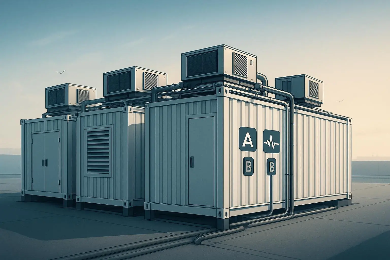
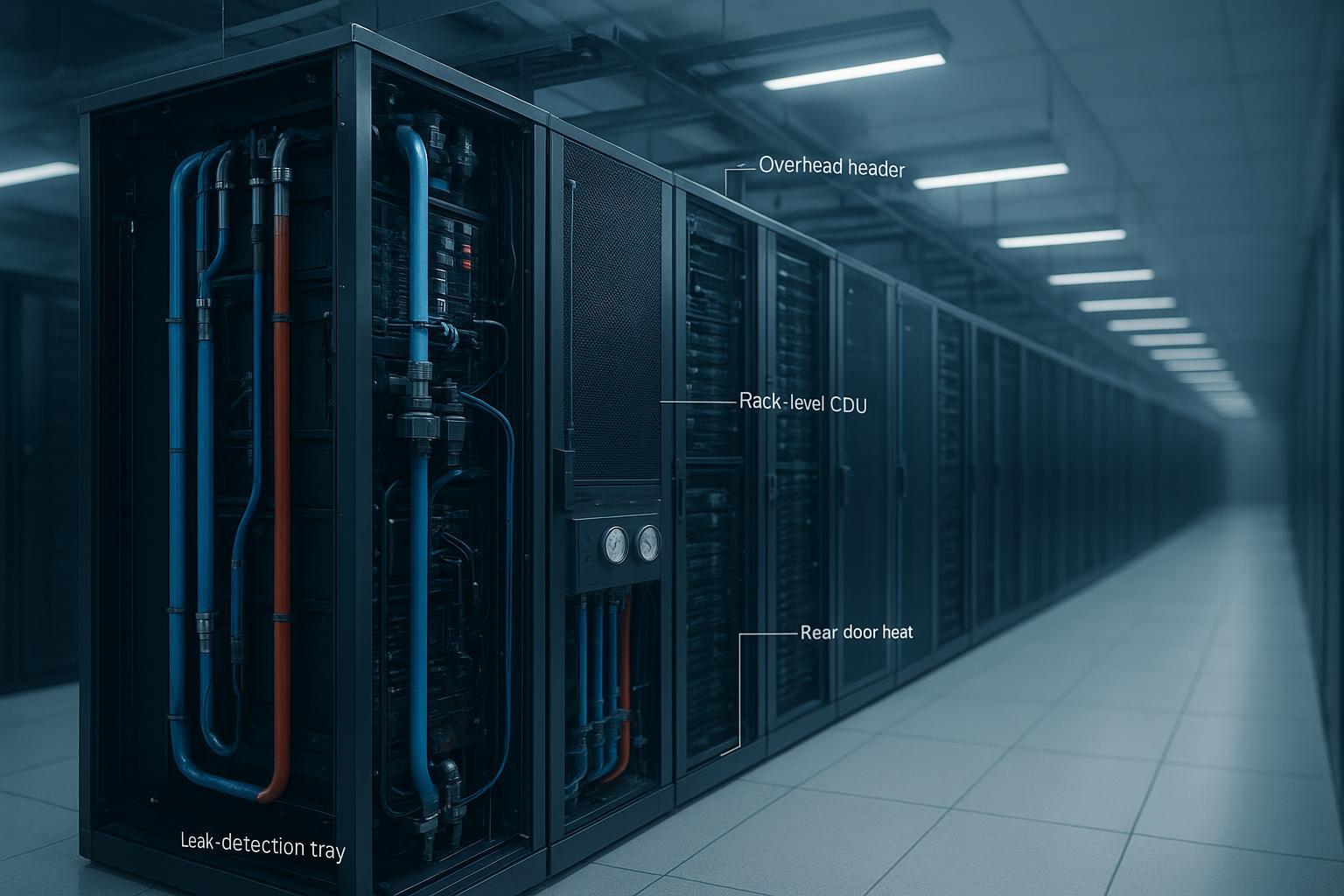
CDUs and redundancy
Use liquid‑to‑liquid CDUs to isolate IT coolant from facility water. For pods, row‑level CDUs simplify maintenance; for single racks, rack‑level CDUs minimize pipe runs.
Redundancy: N+1 pumps per CDU and dual power feeds are standard practice.
Controls: implement differential‑pressure control with minimum‑flow safeguards, warm‑water setpoints, and BMS/DCIM alarm integration.
Filtration and chemistry: staged filtration protects cold plates; maintain treated water or water/glycol to OEM specs and monitor conductivity and corrosion inhibitors.
Reliability fundamentals and controls considerations are discussed in ASHRAE Journal features on data center controls reliability.
Manifolds, distribution, and quick‑disconnects
Plan row headers and in‑rack manifolds with isolation, balancing valves, and drain/fill points. Budget pressure drop across hoses, bends, and plates, then size pumps with margin against expected fouling. Choose dry‑break, dripless quick‑disconnects with clear supply/return coding, in line with the hardware interface practices captured by the Open Compute Project’s Advanced Cooling Solutions program.
Leak detection and safety
Build multiple layers:
Spot sensors in drip trays under manifolds and CDUs.
Distributed leak‑detection cable along trays and risers.
Flow‑imbalance and pressure‑drop logic in CDUs.
Fail‑safe shutoff valves near headers and at the rack to limit spill volume.
ASHRAE TC 9.9’s liquid‑cooling guidance underscores isolation via L2L exchangers and containment strategies for IT spaces, which are especially valuable in retrofits.
Residual air with rear‑door heat exchangers
Direct‑to‑chip handles the hot silicon, but non‑liquid components still add heat. Rear‑door heat exchangers can scrub this residual exhaust at the rack boundary so rooms remain thermally neutral, a well‑documented pairing in high‑density education material from Vertiv.
Power distribution for high density
At 50–200 kW per rack, coordinate electrical and thermal designs from the start. Dual‑feed busways, high‑capacity PDUs or power shelves, and branch coordination must meet local electrical codes. For rack‑level DC distribution in open compute architectures, consult the Open Rack ORv3 repository for bus bar and shelf interfaces.
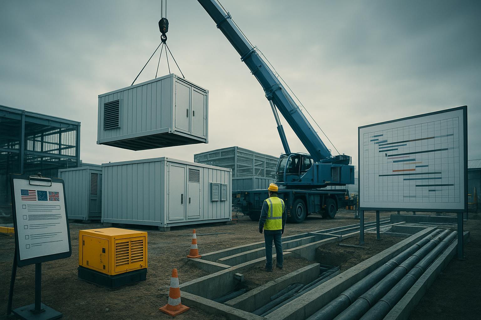
Retrofit playbook for brownfield rows
A staged approach protects availability while ramping capacity. Think of it as “liquid first where it counts, room neutrality next.”
Survey and plan: run a thermal survey and, if possible, CFD to locate candidate rows and airflow interactions. Confirm structural limits, routing paths (overhead is often cleaner than underfloor), and baseline water quality.
Install distribution: add overhead or sidecar headers with isolation and balancing. Mount row manifolds with drip trays and sensors; pre‑wire controls to the BMS/DCIM.
Bring in CDUs: deploy row‑level CDUs with N+1 pumps and dual power; commission control logic, alarms, and valve interlocks.
Cut in racks: add liquid‑ready servers and connect via dripless QDs. Use RDHx where residuals threaten room neutrality. Keep legacy racks nearby on air until cutover windows allow migration.
Validate and expand: run stepped load tests, confirm delta‑T and flows, record KPIs, then scale pod by pod.
Time markers you can use for planning (typical ranges): site assessment 1–2 weeks; detailed design 2–6 weeks; procurement 4–8 weeks; installation 1–3 days per row after headers are in place; commissioning 1–3 weeks depending on loop complexity.
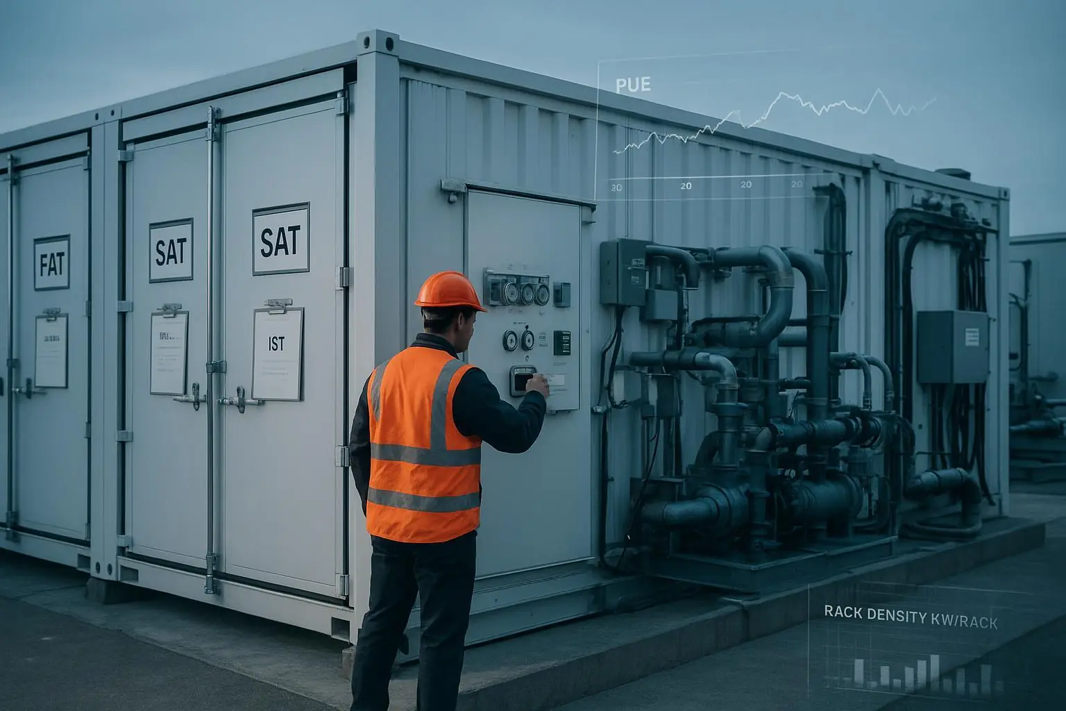
Commissioning and operations
Treat commissioning as a safety‑critical, data‑driven process.
Pressure test and flush: hydrostatic/pressure tests, high‑velocity flushing, then air purging and passivation before production. TC 9.9 contributors have highlighted how air removal can take longer than expected in complex loops; plan sufficient time, as discussed in ASHRAE Journal podcasts featuring TC 9.9 members.
Functional checks: verify valve strokes, sensor calibration, and CDU logic (including fail‑safe isolation). Capture baseline trends for flow, pressure, and temperature.
Thermal acceptance: apply stepped synthetic loads and confirm junction stability, rack‑level delta‑T, and room neutrality with RDHx engaged where installed.
Handover: document loop diagrams, setpoints, alarm thresholds, filter specs, and leak‑response SOPs; integrate KPI dashboards.
Ongoing O&M should include periodic inspection of QDs and seals, filter replacement, water chemistry audits, leak‑drill exercises, and spares management. Keep change logs for any topology or setpoint updates.
Heat reuse and KPI reporting
Warm‑water return from modular liquid cooling opens the door for district or building‑level reuse. Report outcomes transparently using recognized KPI structures:
PUE and WUE reporting are defined in the ISO/IEC 30134 series; align categories and boundary conditions to maintain comparability across sites.
Energy Reuse Factor is mapped in EN 50600‑4‑6; if stakeholders prefer the PUE‑like framing that accounts for reuse, The Green Grid’s ERE definition provides an alternative lens.
Link your acceptance tests to these metrics, then trend them in operations. As you optimize setpoints and flow, track the effect on PUE and any heat‑export fraction for ERF/ERE.
Authoritative resources for definitions and frameworks include ISO/IEC 30134 entries at ISO’s Online Browsing Platform, EN 50600‑4‑6’s ERF mapping, and The Green Grid’s archived paper on Energy Reuse Effectiveness.
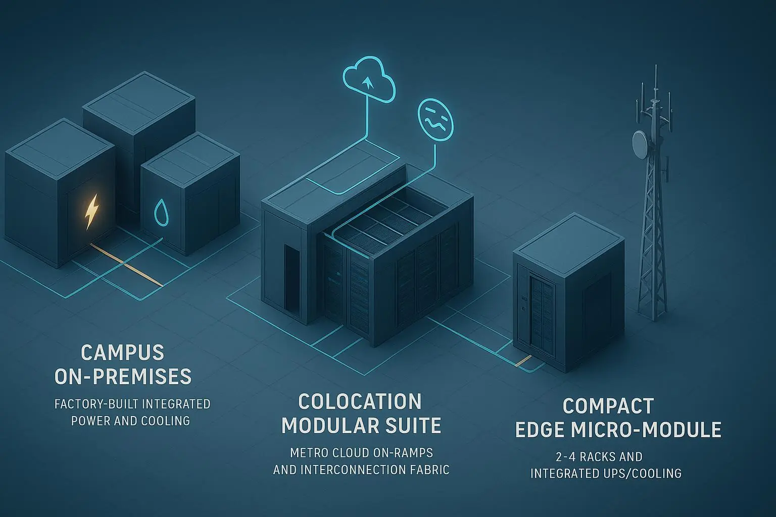
Reference designs you can adapt
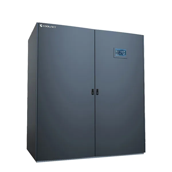
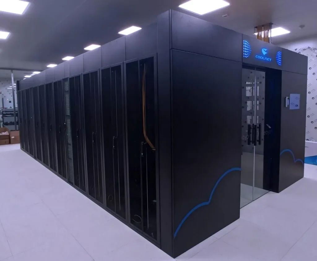
Here are two pod‑level patterns that teams commonly start from. If you’re evaluating repeatable, pod-style rollouts, Coolnet’s MetaRow modular data center is one example of how teams package infrastructure in a modular form factor. Validate all values against device OEM specs, site hydraulics, and standards before use.
100 kW/rack pod (5 racks at 500 kW total)
Cooling: single‑phase direct‑to‑chip on CPUs/GPUs; RDHx per rack for residuals.
Loop: row‑level L2L CDU, N+1 pumps; supply 32–38°C; rack delta‑T target 7–10°C.
Distribution: overhead headers, in‑rack manifolds with dripless QDs; layered leak detection.
Acceptance: stable junction temps under 110% step load; room neutrality within target band; PUE ≤ 1.20 in steady state; WUE ≈ 0.
200 kW/rack pod (4 racks at 800 kW total)
Cooling: single‑phase direct‑to‑chip with tight plate selections; consider two‑phase direct‑to‑chip for highest heat‑flux devices or where facility water is constrained.
Loop: row or dual rack‑level CDUs, N+1 pumps; supply 35–45°C; rack delta‑T target 6–8°C; strict delta‑P budgeting across plates and hoses.
Distribution: enlarged headers/manifolds, short hose runs, precision balancing; aggressive leak detection and auto‑shutoff near racks and row headers.
Acceptance: stable junctions under production plus burst loads; PUE 1.15–1.25 depending on plant; WUE ≈ 0; document ERF/ERE if heat export is active.
What to do next
Decide on the pattern using the matrix, then run a focused thermal survey.
Draft a pod BOM and loop diagram, including CDU redundancy, manifold topology, and leak‑detection coverage.
Build the commissioning script alongside design, mapping each test to a metric and acceptance threshold.
Plan a staged retrofit cutover, reserving calendar windows and spares before the first manifold goes live.
Further reading to ground your design choices in standards and community specs:
Review the ASHRAE Thermal Guidelines 5th edition reference card for liquid water classes and limits.
Read ASHRAE TC 9.9’s white paper on the expansion of liquid cooling for context and hybrid patterns.
Explore the Open Compute Project’s Advanced Cooling Solutions pages for interface practices and safety guidance.
See Vertiv’s educational overview on how rear‑door heat exchangers support high‑density racks for residual heat capture.
For reporting ERF and understanding ERE’s framing, consult EN 50600‑4‑6 and The Green Grid’s archived paper on ERE.
Sources cited in context:
ASHRAE’s Thermal Guidelines 5th edition reference card (2021) defines liquid water classes and temperatures.
ASHRAE TC 9.9 white paper details adoption paths and hybrid nodes in mainstream data centers.
OCP’s Advanced Cooling Solutions project hosts hardware interface and safety practices for liquid cooling.
ISO/IEC 30134 series and EN 50600‑4‑6 define KPI reporting structures; The Green Grid’s ERE paper explains the adjusted reuse metric.
Links (mentioned once each above):
ASHRAE Thermal Guidelines 5th ed. reference card: https://www.ashrae.org/file%20library/technical%20resources/bookstore/supplemental%20files/therm-gdlns-5th-r-e-refcard.pdf
ASHRAE TC 9.9 liquid cooling white paper: https://www.ashrae.org/file%20library/technical%20resources/bookstore/emergence-and-expansion-of-liquid-cooling-in-mainstream-data-centers_wp.pdf
OCP Projects (ACS landing): https://www.opencompute.org/projects
ISO/IEC 30134 index (KPIs): https://www.iso.org/obp/ui/
EN 50600‑4‑6 (ERF metric): https://standards.iteh.ai/catalog/standards/clc/0107ec33-6837-4327-83bd-18621f78d6fb/en-50600-4-6-2020
The Green Grid ERE archive: https://archive.thegreengrid.org/en/resources/library-and-tools/242-WP