Speed, repeatability, and predictable quality are the headline benefits of modular builds. The catch is proving—clearly and consistently—that your modules meet the bar for compliance and resilience across sites and jurisdictions.
This guide takes a US‑first view of the standards that matter, shows how redundancy targets translate into modular topologies, and gives you commissioning and monitoring artifacts you can hand to auditors. The goal is simple: raise assurance while keeping delivery fast.
Key takeaways
Treat standards as a map to evidence, not just logos. UL 2755, NFPA 75/76, Uptime Tier criteria, NIST controls, and EN 50600 each imply specific documents, tests, or logs you should collect.
Design redundancy with performance language (concurrent maintainability, fault tolerance) rather than only shorthands (N, N+1, 2N). Failure-domain separation and continuous cooling are what auditors and certifiers examine.
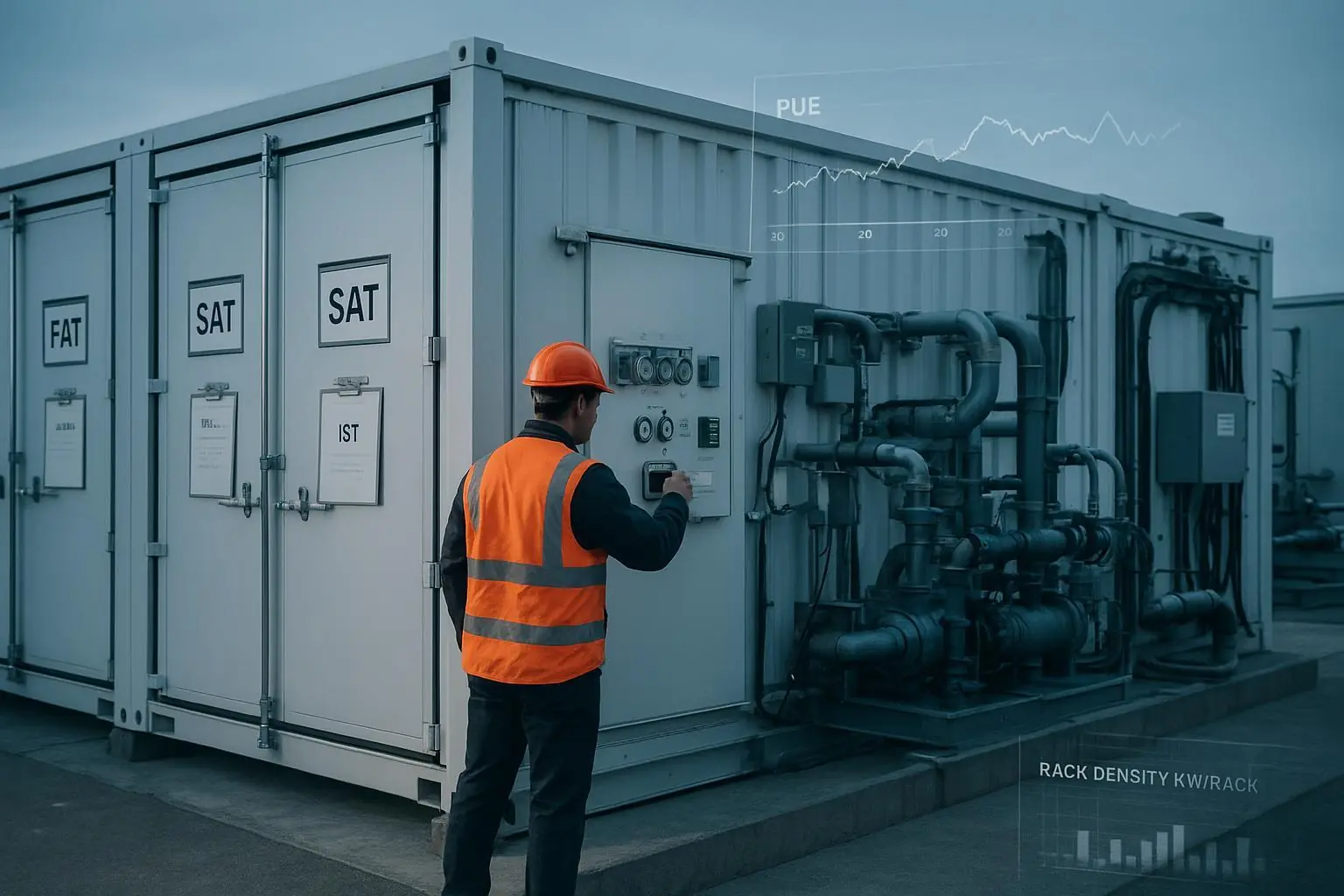
Commissioning is your proof engine: plan FAT, SAT, and IST with witness scripts, acceptance criteria, and instrument IDs; archive everything in a retrievable format.
Build monitoring and log retention to policy from day one. Align telemetry and exports to NIST SP 800-92r1/800-53 expectations so audits don’t become scavenger hunts.
Standardize artifacts across sites (templates, checklists, runbooks). That’s how modular data center compliance resilience scales.
The standards you need to map (US‑first, with global context)
Think of standards as a set of lenses that shape both design choices and the evidence you’ll be asked to produce.
UL 2755 — Prefabricated Modular Data Center Systems. Certification provides a path to evaluate containerized/prefab units as integrated products, streamlining AHJ approvals when completed pre‑shipment and aligning with NEC Article 646. See UL’s program overview in Prefabricated Modular Data Center Testing and Certification (2025) for scope and process details: UL Solutions — Prefabricated Modular Data Center Testing and Certification.
NFPA 75/76 — Fire protection for ITE and telecom facilities. These 2024-cycle documents coordinate with NEC/NFPA 70 and influence detection, suppression, surge protection, and alarm interfaces common to modular and edge sites. For edition status and scope notes, refer to NFPA committee publications: NFPA 75/76 committee reports confirming 2024 editions.
Uptime Institute — Tier criteria (III/IV). Tiers are performance-based: Tier III expects concurrent maintainability; Tier IV expects fault tolerance and continuous cooling. Topology shorthands don’t guarantee outcomes—design, separation, and operations do. Review the public overview: Uptime Institute — Tier Certification overview.
NIST SP 800‑53 Rev. 5 and SP 800‑92r1 — Physical/environmental controls and log management. Map PE-family controls (access, fire, temperature/humidity) to monitoring and testing, and establish log lifecycle requirements (generation, storage, access, disposal) with failure detection and retention to policy. Authoritative starting points: NIST — SP 800 series landing and NIST — SP 800‑92r1 (Cybersecurity Log Management Planning Guide, 2025 draft).
EN 50600 — European framework for data center facilities. If you operate multi‑region portfolios, use EN 50600’s availability classes and subsystem structure to keep your crosswalks coherent. See the official 2024 overview: CEN‑CENELEC — Data Centre Standardization brochure (Edition 11, 2024).
Redundancy and availability—how modular designs meet the bar
Here’s the deal: auditors and certifiers don’t pass a diagram because it says “2N.” They pass a facility because any single failure or maintenance activity behaves within defined performance outcomes.
Concurrent maintainability (Tier III‑aligned example): A row‑level UPS plant configured N+1 with a maintenance bypass lets you service one UPS module, one PDU, or one cooling pump without impacting IT. In modular form, that may be a power skid and a cooling skid with separate control power and isolations. The outcome: planned maintenance has no user impact.
Fault tolerance with continuous cooling (Tier IV‑aligned example): Dual isolated utility/generator paths, independent switchboards, segregated feeders, and two truly separate cooling trains (including controls and backup control power). A single failure anywhere, plus concurrent maintenance, does not impact IT or thermal envelopes.
Failure‑domain thinking in practice: for each component, ask what loses power or cooling if it fails or is removed for maintenance, which alarms should fire, and whether IT remains inside electrical and thermal tolerances; trace control power to avoid shared PLCs or power supplies that break fault tolerance; and validate continuous cooling with calculations you then prove during IST.
Commissioning playbook for modular: FAT, SAT, and IST
Commissioning is where modular data center compliance resilience turns from intent into evidence. Use ASHRAE’s commissioning process to structure documents, roles, and acceptance criteria across phases. For definitions and methodology context, see references to Guideline 0 and Standard 202 in ASHRAE publications (2024 updates and catalog listings): ASHRAE — Publications catalog listing Standard 202 and Guideline 0.
Below is a compact, illustrative matrix you can adapt. Expand with your equipment list and add witness/sign‑off lines.
Phase | System | Test objective | Method | Acceptance notes | Evidence artifact |
|---|---|---|---|---|---|
FAT | UPS | Verify step‑load response and static bypass | Apply 25/50/75/100% steps; observe V/Hz; transfer to/from bypass | Voltage within spec; no alarms; THD within OEM limit | Signed FAT report with plots; instrument IDs |
FAT | Prefab power skid | Protective settings and I/O integrity | Inject trip; verify relays, alarms, E‑stop | Trips per settings; alarms latched | Relay test sheets; settings export |
SAT | Cooling loop | Pump/VFD rotation and flow | Bump tests; measure ΔP/flow | Rotation correct; flow ≥ design min | SAT checklist; trend screenshot |
SAT | Fire detection | Interface to BMS/DCIM | Activate detector; verify signals | All points correct; timestamps aligned | I/O matrix; alarm history export |
IST | Power | Utility loss to generator | Open utility breaker; observe ATS/UPS | No IT impact; ride‑through in envelope | IST script; event timeline |
IST | Mechanical | Loss of primary pump | Shut 1 pump; verify standby start | Supply temps within limit; alarms | IST log; trend plots |
Evidence metadata to capture on every line: test script version, timestamps, roles (vendor QA, owner’s rep, third‑party commissioning agent), instrument serial numbers and calibration dates, deviations and corrective actions, and final sign‑off.
Monitoring and evidence readiness from day one
Design your telemetry with audits in mind. NIST SP 800‑92r1 describes the log lifecycle—generation, storage/transfer, access, retention, and disposal—with monitoring for failures. Pair that with SP 800‑53 Rev. 5 PE controls for what must be observed (access, fire, environmental) and SP 800‑137 continuous monitoring concepts.
A practical starting pattern is to define a log taxonomy (physical access; power/cooling telemetry; control changes; alarm acknowledgments; safety events), assign owners and retention windows aligned to policy, configure alerts on logging failure conditions (storage nearing capacity, collector offline, time‑sync drift), and standardize an export pack per site—past 90 days of critical alarms, 12 months of monthly summaries, change logs for protection settings, and last IST results—stored as hash‑verified PDFs/CSVs with index files. An auditor‑friendly event description might read: “On 2026‑02‑17 14:07:23Z, Utility A loss detected; ATS transferred at 14:07:25Z; UPS ride‑through with no alarms; cooling Train B maintained 72°F inlet. Evidence: event timeline PDF, DCIM trend CSV, ATS log, UPS waveform plots.”
Control‑to‑evidence mapping you can hand to an auditor
Standard/control area | Objective | Evidence to collect |
|---|---|---|
UL 2755 certification | Demonstrate modular unit safety/construction compliance and NEC Article 646 alignment | UL 2755 certificate/listing; construction drawings; labeling photos; installation instructions; factory QA records; AHJ correspondence |
NFPA 75/76 application | Show fire protection design and telecom facility protections | Fire alarm/detection/as‑built drawings; suppression agent data sheets; surge protection device specs/test reports; acceptance test certificates; maintenance logs |
Uptime Tier criteria | Prove concurrent maintainability or fault tolerance with continuous cooling | One‑line diagrams with failure‑domain annotations; maintenance bypass procedures; continuous cooling verification scripts; IST results; operations SOPs |
NIST SP 800‑53 (PE) | Effective physical/environmental controls | Access control procedures; badge/CCTV logs; power/cooling monitoring exports; emergency shutoff locations; fire system test reports; assessment checklists |
ISO/IEC 27001 Annex A (Physical) | Facility controls integrated into the ISMS | Policies/procedures; visitor logs; environmental monitoring reports; incident and corrective‑action records; performance evaluation records |
Commissioning process (ASHRAE) | Verification across FAT/SAT/IST | Commissioning plan; test matrices; scripts; signed reports; issues log; corrective actions; equipment certificates; calibration records |
Log management (NIST SP 800‑92r1) | Logging lifecycle and failure detection | Logging policy; retention schedules; alerts showing detection of failures; sample investigations; change control records; disposal safeguards |
For authoritative context, consult: UL’s modular data center certification program, NFPA 75/76 committee materials (2024 cycle), Uptime Institute Tier overview, NIST SP 800 series hub, NIST SP 800‑92r1, EN 50600 brochure, and ASHRAE catalog reference.
Why modular data center compliance resilience starts with the right redundancy decision
Picking N, N+1, 2N, or 2(N+1) is not about fashion—it’s about business impact (RTO/RPO), site risk, and cost. Use the tiny workbook below to frame discussions across facilities, operations, and compliance.
Inputs:
  - Target RTO (minutes)
  - Target RPO (minutes)
  - Critical load (kW)
  - Acceptable annual downtime (minutes)
  - Failure-rate proxy for a single path (events/year)
  - Cost deltas: CAPEX/OPEX for N, N+1, 2N, 2(N+1)
Logic:
  1) If acceptable annual downtime <= 30 min and RTO <= 5 min → shortlist 2N or 2(N+1)
  2) Else if downtime <= 240 min and RTO <= 30 min → shortlist N+1 (with segmented cooling)
  3) Else → consider N with rapid-repair strategy and scheduled-maintenance windows
  4) For each shortlist option, verify:
     - Failure-domain separation (no shared single points including controls)
     - Continuous cooling under worst credible failure + maintenance
     - Testability in IST (documented)
  5) Compare lifecycle cost vs. risk: choose the lowest-cost option that meets the outcomes
Output:
  - Selected redundancy pattern + commissioning tests required to prove it
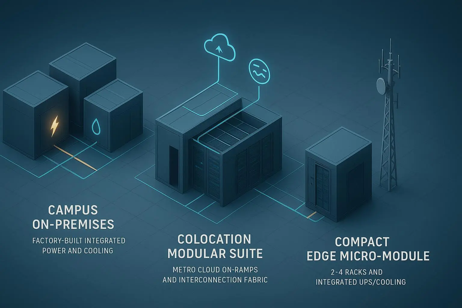
Illustrative example: A 300‑kW edge site with RTO 10 minutes, acceptable downtime 120 minutes/year, and moderate utility reliability. The workbook recommends N+1 with segmented cooling loops and dual control power, plus IST to demonstrate generator transfer during a concurrent pump maintenance. That balances availability with cost while meeting stated outcomes.
Short, anonymized vignette (illustrative)
A regional banking program standardized its 8‑rack modular pods across five cities. Baseline (pre‑modular) average commissioning defects per site were 37, and first‑year incident MTTR averaged 110 minutes. After adopting a common FAT/SAT/IST matrix, a standard DCIM export pack, and Tier‑language design reviews, the illustrative outcomes were a reduction in commissioning defects to 15 per site (‑59%), a drop in first‑year facility‑related MTTR to 65 minutes (‑41%), and audit prep time shrinking from three weeks to five days because evidence was uniform across sites. These are hypothetical but realistic figures used to illustrate the impact of standardization; validate with your own metrics and auditor feedback.
What to do next
Build your control‑to‑evidence map using the table above, then assign owners and retention windows.
Select a redundancy target using the workbook, and schedule IST scenarios that directly prove the outcome language (concurrent maintainability or fault tolerance with continuous cooling).
Formalize a commissioning plan (FAT/SAT/IST) with witness requirements and instrument metadata.
Define a site‑standard DCIM/telemetry schema and logging policy aligned to NIST SP 800‑92r1.
Pre‑engage your AHJ and certification bodies early (UL/NFPA/Uptime as applicable) to align on documentation.
Pilot on one site, capture lessons, freeze templates, and then roll out to the portfolio.