Rear-door heat exchangers (RDHx) can reduce facility energy in mixed estates moving from optimized air toward higher-density cooling—when they’re integrated and controlled correctly. In many 20–50 kW/rack scenarios, shifting most rack exhaust heat to a liquid loop raises chilled-water setpoints, cuts CRAC/CRAH fan and compressor work, and can enable more hours of economization. The net effect on PUE depends on water temperature, coil approach, airflow resistance, and controls.
Key takeaways
Under favorable boundary conditions (elevated supply water ~27°C/80.6°F, controlled airflow/containment, dew‑point management), rear-door heat exchangers PUE gains commonly land in the ~5–15% range versus well‑run all‑air rooms; results vary with climate and baselines.
Passive vs active RDHx: passive doors lean on server fans and suit many 20–30 kW/rack use cases; active doors add EC fans for airflow stability and typically extend to 30–50 kW/rack and above (model‑dependent).
Integration quality drives outcomes: chilled‑water or CDU secondary loops with dew‑point override, filtration, and proper metering determine both efficiency and reliability.
Retrofits can proceed rack by rack with short maintenance windows when manifolds, quick‑connects, and isolation are prebuilt; plan method statements and rollback paths.
Validate any PUE claim with consistent 12‑month metering before/after the retrofit; document boundary conditions and setpoint changes.
For where RDHx fit between optimized air and liquid paths at moderate densities, see the internal knowledge base overview energy‑efficient cooling for 20–40 kW racks.
When rear-door heat exchangers lower PUE
RDHx capture rack exhaust at the source and transfer most sensible heat to a water loop. That reduces room air mixing, so CRAC/CRAH units see lower return loads and can run lower fan speeds and, where chillers are present, at higher chilled‑water setpoints with reduced compressor work. Elevated supply water (for example, around 27°C) expands free‑cooling windows in suitable climates, improving net energy use.
In 2025, an engineering overview described how optimized RDHx coils running at higher water setpoints can reduce chiller power materially and improve overall efficiency; it quoted examples like a 32% reduction in chiller energy and a PUE improvement around 7% under defined assumptions—directional rather than universal figures, but informative for planning, according to Copper.org’s RDHx coil optimization article (2025). Knowledge hubs from 2024–2025 emphasize operating at higher water temperatures and using RDHx to enable more hours of economization, which can lower cooling energy and thus PUE; see the vendor‑neutral explainer by TRG Data Centers. In short: with good airflow control, elevated water setpoints, and dew‑point safeguards, RDHx typically reduce cooling energy. The headline number depends on the baseline and local climate.
Passive vs active RDHx at a glance
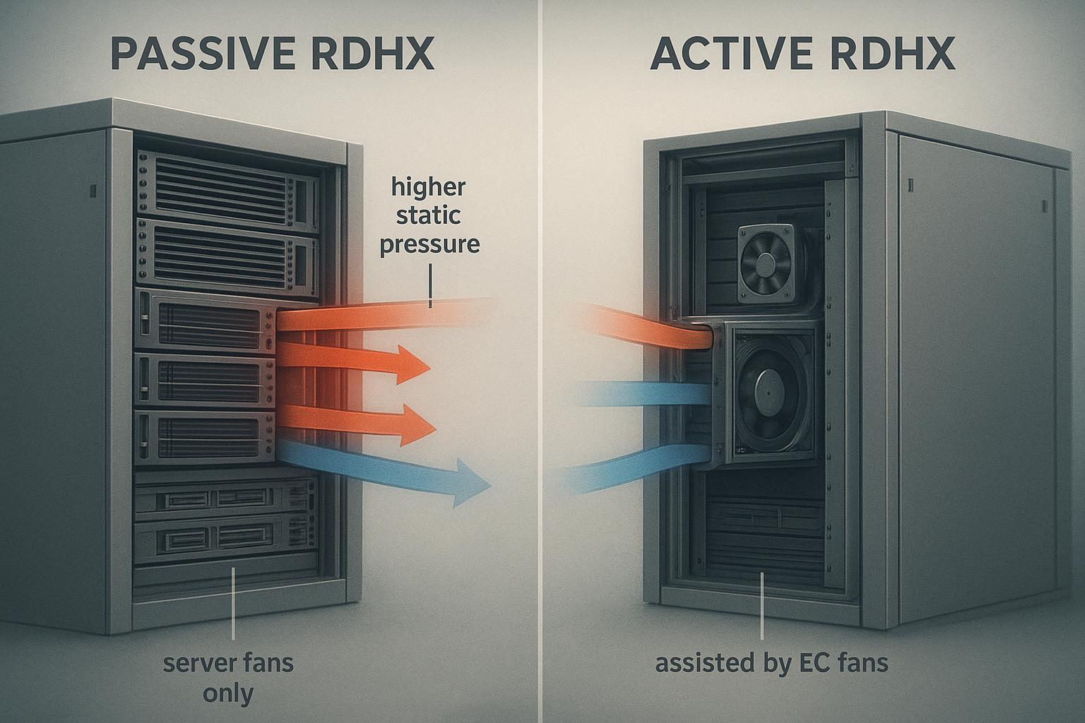
Passive RDHx rely on server fans to pull/push exhaust through the coil. The added coil pressure drop can raise server‑fan work but avoids door fan power, fitting many 20–30 kW/rack scenarios when airflow paths are well managed. Active RDHx add EC fans on the door to stabilize airflow and reduce static pressure seen by server fans. They add several hundred watts per door (model‑dependent) but support higher densities—commonly 30–50 kW/rack and above.
If you’re evaluating retrofit options, one practical check is whether your rack layouts and door clearances can accommodate an RDHx swap without reworking the entire row. For a product-oriented example of a chilled‑water rear‑door heat exchanger configuration, see Coolnet’s page on a chilled‑water rear‑door heat exchanger for data center cooling (specs vary by model and site conditions).
Comparison (directional; verify with OEM data):
Attribute | Passive RDHx | Active RDHx |
|---|---|---|
Airflow source | Server fans only | Server fans + EC fans in door |
Typical density envelope | ~20–30 kW/rack | ~30–50 kW/rack and higher |
Additional power on door | None | EC fan power (hundreds of watts) |
Pressure/airflow stability | Sensitive to coil ΔP and server‑fan curves | More stable; tunable via fan speed |
Pros | Lower door power, simpler O&M | Better high‑density support, smoother control |
Cons | May raise server‑fan energy and noise | Adds door fan power and maintenance |
For concise primers, see Supermicro’s RDHx fundamentals and the vendor‑neutral overview by TRG Data Centers.
Integrating RDHx with CRAC/CRAH and chilled-water/CDU loops
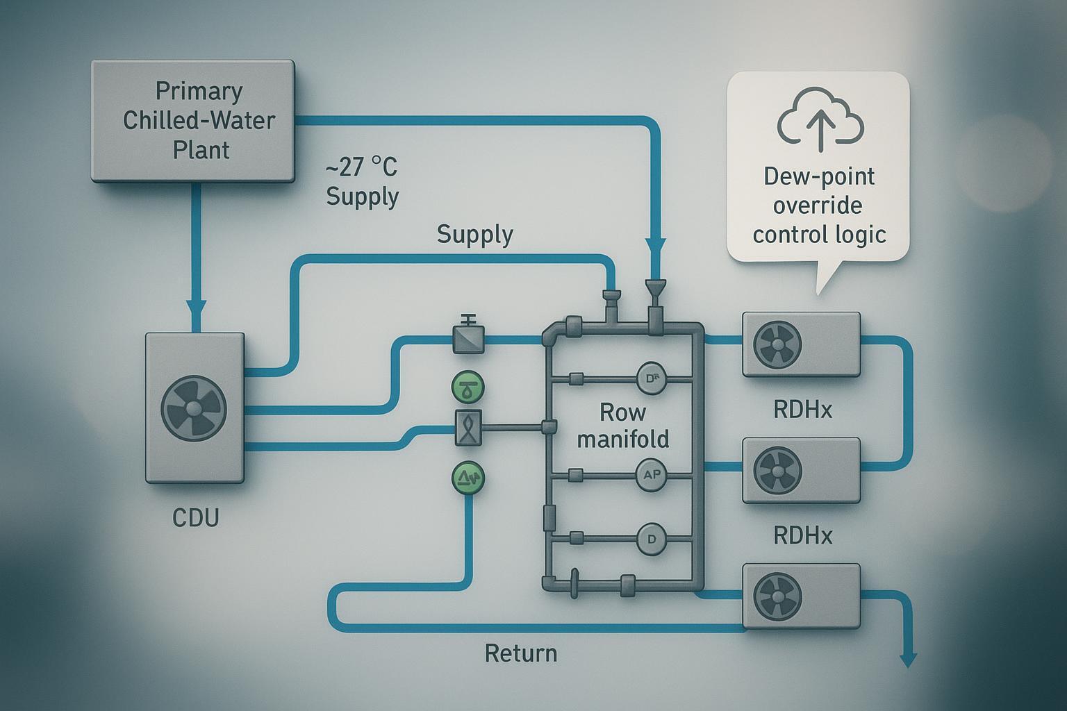
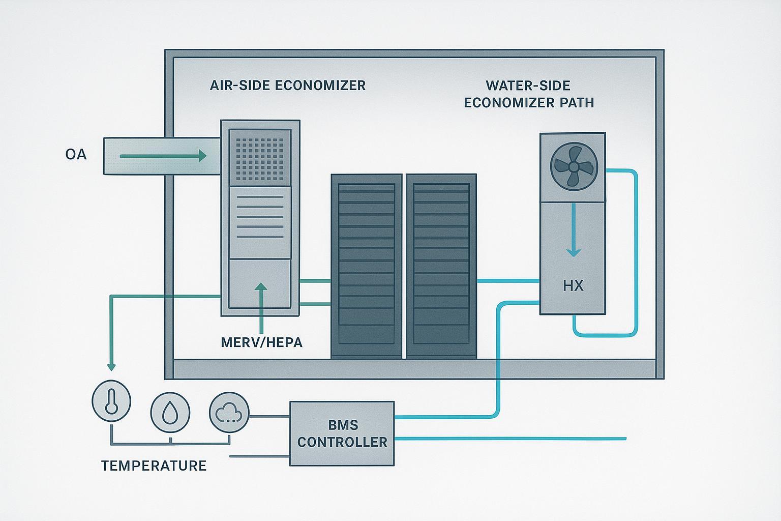
Retrofit‑first patterns for mixed estates: RDHx remove most rack sensible heat and discharge tempered air back into the room while CRAC/CRAH units control room humidity and handle residual loads. Connect RDHx to facility chilled water via row manifolds/headers with isolation and balancing valves, strainers, flow meters, and differential‑pressure sensors. Running higher supply temperatures (e.g., ~27°C) reduces compressor work and increases free‑cooling hours where climate allows. Alternatively, use a coolant distribution unit (CDU) for hydraulic/thermal decoupling; CDUs maintain secondary supply above ambient dew point and simplify commissioning and metering.
Controls and condensation avoidance A common CDU control approach is to keep the secondary supply temperature above the room dew point (sometimes described as a “dew‑point” or “condensation avoidance” control), reducing condensation risk at hoses and coils. Instrumentation to plan for includes ambient temperature/RH/dew point, coil supply/return temperature, differential pressure across coils, manifold flow and pressure sensors, valve actuator position feedback, and BMS/DCIM alarming. For a neutral overview of CDUs and dew‑point control concepts, see Airedale’s “Understanding Coolant Distribution Units (CDUs)” (2024), and for manifolds, see Tate’s explainer on liquid cooling manifolds in high‑density data centers (2025).
Retrofit downtime — what to plan for
Public, operator‑verified per‑rack swap times are scarce, but RDHx are widely described as retrofittable with minimal disruption using quick connects and rack‑by‑rack rollout. As a planning baseline: prebuild the secondary loop and row manifolds with isolation/bypass, prefit dripless quick‑connects near each rack, and sequence changeovers during maintenance windows. Many programs target sub‑hour to a few hours per rack depending on site prep, space, and whether a brief power‑off is required—placeholders to be confirmed by method statements and a pilot run. Directional references include USystems’ retrofit guidance and Supermicro’s quick‑connect kits brochure.
Planning context: For density migration and growth road‑mapping, see the internal article data center capacity planning explained.
Related solution context: If you’re mapping an incremental path from optimized air to rack‑level liquid assist, Coolnet’s precision cooling solutions overview can help you compare deployment patterns alongside your existing CRAC/CRAH baseline.
Modeling and validating rear-door heat exchangers PUE impact
Quick refresher: PUE is the ratio of total facility power to IT power. Keep metering boundaries identical before and after a retrofit and log across seasons. For more on definitions and boundaries, see the internal primer Modular data center TCO FAQ.
Worked example (illustrative, medium depth)
Scenario and assumptions
Pod: 10 racks at 35 kW/rack → 350 kW IT power.
Baseline: CRAH + chiller plant at ~10/15°C water; decent but not perfect containment.
Retrofit: Active RDHx on each rack supplied by a CDU secondary loop at ~27°C with dew‑point override; CRAH retained for residuals/humidity.
Directional evidence (not site‑metered): higher water temperatures can reduce chiller compressor energy and improve overall PUE, summarized in Copper.org’s engineering article (2025).
Illustrative energy balance
Baseline cooling power (simplified): 210 kW (assume 0.6 kW/kW IT for this legacy baseline; adjust per site).
After RDHx: chiller share reduced by ~32% on the chiller portion; CRAH fan power reduced by ~70% of its share; add RDHx fans and CDU pumps.
Component | Baseline | After RDHx | Notes |
|---|---|---|---|
Chiller power | 147 kW | 100 kW | ~32% reduction on chiller portion (directional) |
CRAH fan power | 63 kW | 19 kW | ~70% reduction on residual room load |
RDHx door fans | 0 kW | 3 kW | 10 doors × 0.3 kW average |
CDU/pumps | 0 kW | 10 kW | Secondary loop overhead |
Total cooling | 210 kW | 132 kW | Net −78 kW (≈−37%) |
Illustrative PUE
Baseline PUE ≈ (350 + 210) / 350 = 1.60.
After RDHx PUE ≈ (350 + 132) / 350 = 1.38.
Improvement ≈ 13.8% (absolute −0.22). Real‑world values depend on climate, redundancy, and setpoints; treat this as planning‑level.
Validation steps (aligned to industry guidance) Document a pre‑retrofit 12‑month baseline; keep identical metering boundaries after deployment and log another 12 months to cover seasonality; annotate setpoint changes (higher water temps), redundancy states, and economizer utilization. Industry bodies emphasize consistent boundaries and caution against cross‑site comparisons; see the 2024 survey/reporting guidance from Uptime Institute and the origin material from The Green Grid.
Reliability and maintenance — overview SOP pointers
Common risks include condensation (if coolant supply approaches room dew point), leaks/valve faults, water quality issues that cause fouling or corrosion, and coil fouling that raises differential pressure. A pragmatic cadence many operators adapt: quarterly inspections and strainer checks with valve actuation tests and BMS alarm reviews; semiannual coolant chemistry checks with flow/DP sensor verification; annual pressure/leak testing, leak‑detection verification, CDU dew‑point control tests under simulated high‑RH, and insulation/vapor‑barrier inspections. For general, neutral guidance on environmental and humidity/dew‑point management principles in data centers, see Packet Power’s overview “Understanding Humidity Monitoring in the Data Center” (2023).
Quick decision cues for hybrid estates
20–30 kW/rack with disciplined airflow: start with passive doors; above ~30–50 kW/rack or volatile loads: shortlist active doors.
Favor a CDU‑backed secondary loop with dew‑point override and proper instrumentation if room humidity varies seasonally.
Raise supply water temperatures (within OEM/ASHRAE envelopes) to expand economizer hours; confirm with chiller plant engineering.
Pilot on a small set of racks first; meter thoroughly and define acceptance bands before broad rollout.
Keep CRAH/CRAC units for humidity and residuals; retune fan setpoints after RDHx commissioning.
For migration paths toward AI/HPC densities and when to move beyond RDHx to direct‑to‑chip, the internal guide hybrid paths to scale AI cooling offers planning context.
If you need a concrete reference point for retrofit packaging (manifolds, quick connects, and commissioning expectations), Coolnet also publishes a product example of a rear‑door heat exchanger with chilled‑water integration that you can use as a checklist starter before you request OEM submittals.
Footnotes on terminology and scope
This FAQ uses “rear‑door heat exchangers PUE” phrasing for search clarity; rigorous PUE evaluation requires consistent metering boundaries and 12‑month data. Ranges cited are directional, with sources identified inline and dated 2024–2026.