Designing an AI/HPC hall for 20–40 kW per rack puts you squarely in the crossover zone where air begins to struggle and liquid approaches deliver outsized efficiency. If your site sits in a cold or temperate climate and your mandate is to minimize PUE while staying mindful of WUE and creating future ERE upside, this guide gives you a standards‑aligned, data‑backed path to decisions you can defend in design reviews and audits.
You’ll find a quick comparison of air, RDHx, direct‑to‑chip liquid (cold plates), immersion, and economizers; a concise metrics primer; climate and altitude modifiers; deep dives on each technology; and a practical blueprint for hybrid, partitioned halls that meet today’s 30 kW racks and tomorrow’s higher densities.
Key takeaways
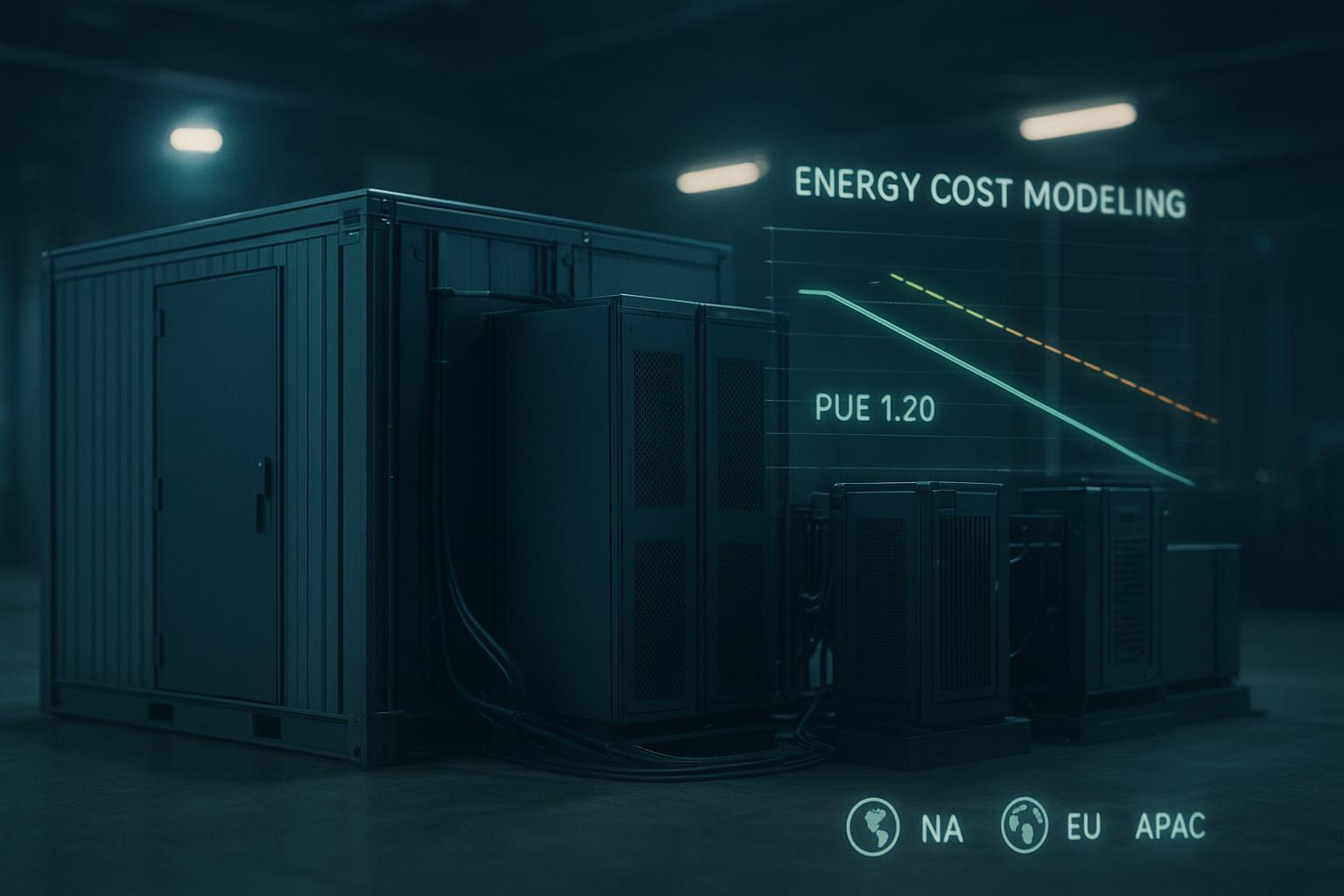
In cold/temperate climates, economizers plus higher IT inlet temperatures within ASHRAE‑recommended envelopes can materially reduce non‑IT energy, lowering PUE; liquid approaches expand those economizer hours by enabling warmer supply/return loops, per the guidance in the U.S. DOE’s 2024 Best Practices for Data Centers.
Between 20 and 40 kW per rack, rear‑door heat exchangers (RDHx) often provide the best step‑change in efficiency without abandoning air entirely, provided dew‑point control, water quality, and pump/fan penalties are engineered correctly and validated against vendor specs and field data.
Direct‑to‑chip (cold plates) and immersion unlock warm‑water operation and strong heat‑reuse potential, which can improve the energy‑reuse picture captured by ERE; open‑access life‑cycle evidence shows both reduce operational energy and blue‑water consumption relative to air‑only baselines.
Altitude and humidity change the calculus: air capacity derates with elevation, shrinking the safe envelope for air‑dominant designs; arid regions impose tight WUE constraints on evaporative strategies, tipping choices toward dry coolers and closed liquid loops.
For new‑build AI/HPC halls, a zoned hybrid (air containment + RDHx and/or cold plates) yields resilient capacity today and a migration route to higher densities without ripping out the entire MEP backbone.
Quick comparison by rack density and metrics
Cooling family | 20–40 kW/rack suitability | PUE impact (directional) | WUE/ERE notes | Climate fit (cold/temperate baseline) |
|---|---|---|---|---|
Optimized air (containment + CRAH/CRAC) | Upper 20s to ~30–40 kW depending on airflow discipline | Improves with economizers and higher inlets; fan power rises at higher loads | Potentially low WUE with dry cooling; limited ERE unless heat captured upstream | Strong where economizer hours are abundant; altitude derating applies |
RDHx (rear‑door heat exchangers) | Well‑matched to 20–40 kW; offloads most rack heat at source | Lowers pPUE by reducing room sensible load; modest pump/fan overheads | Closed water loops keep WUE low; moderate ERE potential with warm returns | Excellent in cold/temperate climates with dry coolers or water‑side economizers |
Direct‑to‑chip (cold plates) | Comfortable at 30–40 kW and above for CPU/GPU heat | Enables warm‑water loops and dry coolers; strong pathway to low pPUE | Low WUE in closed systems; high ERE potential via high‑grade heat | Strong across climates; excels where evaporative water is limited |
Immersion (single/two‑phase) | Highest densities; minimal air reliance | Lowest room‑side overhead; facility pumps/heat rejection dominate | Closed loops can minimize WUE; very strong heat‑reuse prospects | Climate‑agnostic for ITE; heat rejection strategy decides PUE/WUE |
Air‑/water‑side economizers | Not a rack technology; multiplies system efficiency | Cuts compressor hours; can drive very low non‑IT energy in cold seasons | Air‑side: low WUE; water‑side evaporative: higher WUE; dry coolers: low WUE | Best in cold/temperate climates; windows shrink in hot/humid regions |
Note: “PUE impact” is shown directionally; actual results depend on boundary selections, setpoints, and instrumentation.
Metrics that matter: PUE, WUE, and ERE
Power Usage Effectiveness (PUE) expresses total facility energy divided by IT equipment energy. It is the industry’s headline efficiency KPI and the one many boards and regulators recognize. For accessible context, strategies, and common pitfalls, see the U.S. Department of Energy’s 2024 Best Practices Guide for Data Center Design, which emphasizes economizers and higher inlet temperatures within recommended envelopes as first‑order levers to lower non‑IT energy.
Water Usage Effectiveness (WUE) accounts for site water consumption per unit of IT energy (L/kWh). The formal definition and boundary clarifications originate from The Green Grid’s metric series; the WUE white paper is cataloged in The Green Grid library (account sign‑in typically required) and should guide how you count evaporative make‑up, humidification, and other water uses.
Energy Reuse Effectiveness (ERE) complements PUE by crediting useful energy exported outside the data center boundary. When you adopt warm‑water liquid cooling and can hand off higher‑grade heat to a district loop or a heat pump, ERE can improve even if raw PUE does not change much. Formalism for ERE also traces to The Green Grid’s publications; treat ERE as a planning lens alongside PUE/WUE rather than a replacement.
For PUE context and accessible best practices, reference the DOE’s 2024 guide: see the discussion of economizers and inlet temperatures in the Best Practices for Energy‑Efficient Data Center Design (2024).
For metric definitions and boundary details, consult The Green Grid’s library and WUE WP#35 index in the library‑and‑tools section.
Authoritative resources:
According to the U.S. DOE’s open guide, “economizers and higher inlet temperatures reduce compressor energy” in cold/temperate climates; see the Best Practices Guide for Energy‑Efficient Data Center Design (2024): https://www.energy.gov/sites/default/files/2024-07/best-practice-guide-data-center-design_0.pdf
The Green Grid’s library lists WUE (WP#35) and related PUE/ERE papers that establish formulas and boundaries: https://www.thegreengrid.org/en/resources/library-and-tools/238-WP%2335—Water-Usage-Effectiveness-(WUE):-A-Green-Grid-Data-Center-Sustainability-Metric and the archive index: https://archive.thegreengrid.org/en/resources/library-and-tools/238-WP
Climate and altitude: when economizers shine — and when they don’t
Cold and temperate climates are your friend when the goal is energy‑efficient cooling for 20–40 kW racks. Air‑side economizers and water‑side free cooling can slash compressor hours for long stretches of the year if you set realistic supply temperatures and maintain tight airflow management.
Two caveats shape real‑world outcomes:
Altitude derating for air. ASHRAE’s Thermal Guidelines (5th ed.) specify that the maximum allowable dry‑bulb temperature derates with elevation—subtract roughly 1°C for every 300 m above 900 m. Practically, this shrinks the reliability envelope for air‑dominant zones at elevation and often nudges designs toward liquid‑dominant strategies. See ASHRAE’s publicly available reference card for details: https://www.ashrae.org/file%20library/technical%20resources/bookstore/supplemental%20files/therm-gdlns-5th-r-e-refcard.pdf
Humidity and water policy. Air‑side economizers are attractive in cold seasons, but water‑side evaporative strategies raise WUE. In arid or water‑constrained regions, favor dry coolers and warm‑water liquid loops to keep WUE low while preserving efficiency.
For compliance framing in high‑density halls, review ASHRAE Standard 90.4 (2022 edition with 2024 addendum g), which clarifies expectations for mechanical system efficiency and can influence your permitted design space: https://www.ashrae.org/file%20library/technical%20resources/standards%20and%20guidelines/standards%20addenda/90_4_2022_g_20240131.pdf
Technology deep dives for 20–40 kW/rack
Optimized air — containment and economizers done right
Executive view: Air can carry you into the upper 20s and sometimes to ~30–40 kW per rack in cold/temperate climates, but only with disciplined airflow (hot/cold aisle containment, sealed bypass, calibrated CRAH/CRAC fan control) and generous economizer windows. Fan energy rises sharply as you push more air through tighter paths; at some point, liquid at the source becomes the more efficient path.
Engineer’s notes:
Use raised supply temperatures within ASHRAE recommended bands to enlarge economizer hours and reduce compressor work, as emphasized by the U.S. DOE Best Practices (2024).
Treat containment and leakage (bypass and recirculation) as first‑class design parameters—poor seals erase economizer gains.
Expect diminishing returns as rack heat flux grows; verify fan curves and static pressure limits to avoid jarring transitions in control behavior.
Rear‑door heat exchangers — strong fit for 20–40 kW
Executive view: RDHx removes heat at the rack exhaust, dramatically cutting room sensible load while keeping standard form factors and service models. At 20–40 kW per rack, RDHx is often the fastest route to lower pPUE without re‑platforming the IT.
Engineer’s notes:
Dew‑point control is non‑negotiable. IBM’s RDHx documentation specifies that supply water must be kept above room dew point; systems should measure dew point and auto‑adjust water temperature to avoid condensation. See IBM’s RDHx specifications for model 1164‑95X: https://www.ibm.com/docs/en/power9/p9had/p9had_1164_95x_rdhx.html
Hydronic envelope and pressure drop. Representative vendor data shows flow ranges on the order of tens of liters per minute per door and pressure drops in the tens to low hundreds of kPa depending on model and flow; size pumps and valves for your coil’s ∆T and permissible drop, and validate against pump curves.
Secondary loop isolation and water quality. Follow secondary (isolated) loop designs with filtration and proper materials to protect IT and maintain capacity over time; IBM’s secondary loop guidance outlines typical components and specs: https://www.ibm.com/docs/P8DEH/p8ebe/p8ebe_waterdelspecssecondary.htm
Energy overheads and capture efficiency. Peer‑reviewed analysis (NSF‑hosted) provides measured perspectives on RDHx capture efficiency, coil ∆T, and auxiliary energy; use such results to bound expectations and commissioning targets: https://par.nsf.gov/servlets/purl/10536111
What this means for energy‑efficient cooling for 20–40 kW racks: in cold/temperate climates with dry coolers, RDHx can keep WUE low and extend free‑cooling operation, helping you drive down pPUE while preserving familiar rack ergonomics.
Direct‑to‑chip liquid cooling — warm water, low overheads, heat‑reuse ready
Executive view: Cold plates pull most chip heat out of the air path, enabling warmer facility return temperatures and efficient dry‑cooler rejection. That widens the “compressor‑off” window in cold/temperate climates and sets you up for heat reuse where a district sink exists.
Engineer’s notes:
Facility interfaces typically include in‑row or room CDUs with dual‑pump redundancy, plate heat exchangers, and monitored supply/return temperatures. Warm‑water operation (for example, 30–45°C supply to secondary) often pairs well with dry coolers in cold/temperate sites.
Controls tune pump speed to meet temperature targets while minimizing hydraulic penalties. Size expansion vessels and buffer volumes to stabilize transients.
Evidence base: An open‑access, peer‑reviewed life‑cycle assessment reports that cold‑plate systems reduce operational energy use and blue‑water consumption versus air‑only baselines, with two‑phase immersion showing the largest reductions among liquid options. See the 2025 study hosted by PMC: https://pmc.ncbi.nlm.nih.gov/articles/PMC12058514/
Immersion cooling — density headroom and stable thermals
Executive view: Immersion minimizes dependence on room air, offering stable chip thermals at very high densities. Facility energy then concentrates in pumps and heat rejection, often simplifying the path to low pPUE in climates where dry coolers suffice.
Engineer’s notes:
Single‑phase immersion uses a dielectric fluid with pumped circulation through a facility heat exchanger; two‑phase uses the working fluid’s phase change for efficient heat transfer.
Service models and hardware compatibility affect project risk and timeline; plan for handling fluids, tank ergonomics, and field service workflows.
The same 2025 life‑cycle assessment cited above reports strong reductions in energy demand and water use for immersion approaches relative to air baselines: https://pmc.ncbi.nlm.nih.gov/articles/PMC12058514/
Air‑ and water‑side economizers — the multipliers
Executive view: Economizers multiply the efficiency of both air and liquid systems in cold/temperate climates by eliminating or reducing compressor work for long stretches. Setpoint strategy and filtration/contamination control (for air‑side) determine how much of the year you can run in a free‑cooling state.
Engineer’s notes:
DOE’s 2024 Best Practices outlines how higher inlet temperatures and economizers pair to reduce non‑IT energy; dry coolers keep WUE low, while evaporative water‑side free cooling raises WUE but may be acceptable where water is abundant and policy permits: https://www.energy.gov/sites/default/files/2024-07/best-practice-guide-data-center-design_0.pdf
Coordinate economizer logic with liquid setpoints. Warm‑water liquid (D2C or RDHx coils) enables higher free‑cooling hours from dry coolers, especially in cold/temperate climates.
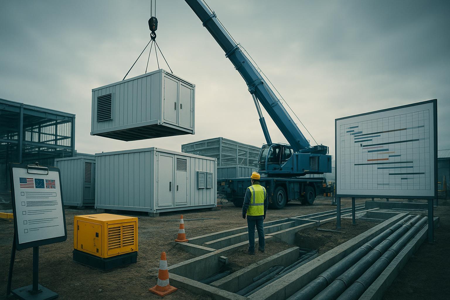
Designing hybrid, partitioned AI/HPC halls
A greenfield AI/HPC hall benefits from zoning: maintain an optimized air‑contained block for moderate‑density racks and pair it with RDHx and/or direct‑to‑chip zones for 30–40 kW racks (and a roadmap to higher). Supply a warm‑water secondary loop with CDUs and dry coolers; keep a clear separation between facility water and IT‑adjacent loops; and meter sub‑systems so you can compute pPUE for each zone.
Example in context: In a cold‑climate 30 kW/rack block, a closed‑loop RDHx row on a warm‑water secondary loop to dry coolers can keep WUE very low while maintaining compressor‑off operation for much of the year. A neighboring direct‑to‑chip zone can export higher‑grade heat for reuse when a district sink exists, improving the site’s ERE. Vendors implement these patterns with variations; for instance, Coolnet supports hybrid deployments that combine RDHx and cold‑plate loops under a monitored CDU backbone for new AI halls, aligning with the control strategies and envelopes discussed here: https://www.coolnetpower.com/
Sizing and BOM walkthrough for a 30 kW/rack zone
This worked example shows the elements you’ll specify and where energy overheads hide. Treat values here as planning placeholders; bind final selections to your weather file, equipment datasheets, and commissioning tests.
Envelope and setpoints
Target rack load: 30 kW; IT inlet within ASHRAE recommended range for your class.
RDHx coil approach: Sized to capture the majority of rack exhaust heat with supply water held above room dew point (active control). For D2C, set secondary supply/return temperatures in the warm‑water range compatible with dry coolers.
Hydronic components (secondary loop)
CDU with dual redundant pumps and plate heat exchanger sized for the row’s total kW plus margin; N+1 pump sizing and VFDs for part‑load efficiency.
Filtration to vendor spec; glycol percentage and inhibitors per local freeze and corrosion policy.
Instrumentation: supply/return temperatures, differential pressure, flow meters per branch, and dew‑point sensors in the white space for RDHx.
Air system coordination
Maintain hot/cold aisle containment; CRAH fans on pressure/temperature control with setpoints raised to expand economizer windows.
Ensure sealing around RDHx doors and cable cutouts to avoid bypass.
Heat rejection
Dry coolers sized for design‑day rejection at warm‑water setpoints; VFD fans with ambient tracking. If water‑side economizers are used, document expected WUE and policy constraints.
Energy sensitivities to watch
Fan affinity laws: small increases in airflow can mean large fan‑power jumps; favor source‑side liquid removal to reduce fan work.
Pump curves: select near best‑efficiency points at common operating flows; avoid throttling for control where a VFD can do the job.
Economizer hours: verify with local weather files and your chosen setpoints; this drives your achievable non‑IT energy floor.
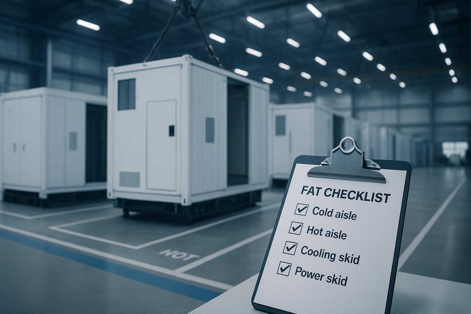
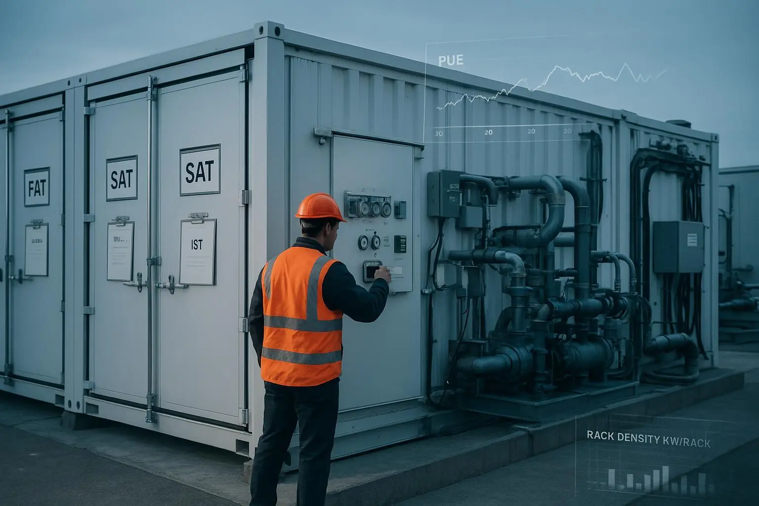
Implementation checklist — commissioning and metering
Validate meter boundaries for PUE, pPUE, WUE, and ERE before energization; install revenue‑grade meters on IT, mechanical distribution, and heat‑recovery subsystems.
Commission dew‑point sensing and water‑temperature control for RDHx; verify condensation avoidance across humidity swings.
Pressure‑test and flush secondary loops; confirm filtration levels and chemical treatment per materials and vendor guidance.
Tune control loops: CRAH fan control, CDU pump VFDs, dry‑cooler fan tracking, and economizer switchover logic; document all setpoints and deadbands.
Run seasonal simulations (or staged tests) to validate economizer windows and dry‑cooler capacity at expected ambient temperatures.
Establish O&M routines: leak detection checks, water‑quality sampling, strainer cleaning, valve actuation tests, and trend‑log reviews.
Operations and maintenance — keeping efficiency stable
Efficiency drifts without attention. Think of it this way: a crisp control sequence on day one becomes a collection of overrides by day 300 unless you monitor and recalibrate.
Water treatment and cleanliness maintain coil heat‑transfer rates and pump efficiency. Schedule lab sampling and filtration checks; track ∆T and pressure trends to catch fouling early.
Controls tuning should be revisited quarterly or after major IT changes. Review economizer switchover points seasonally to match updated weather realities.
Air management requires discipline: restore blanking panels, seal cable openings, and verify containment integrity during every change window.
Document changes and trend logs so you can separate true load growth from control creep; that’s how you protect the gains you modeled on paper.
Where to go next
If you’re mapping a hybrid journey across RDHx, direct‑to‑chip, or immersion, extended reading on architecture options and deployment trade‑offs can help plan your roadmap. See this neutral overview for more context: the Ultimate Guide to AI Data Center Cooling hosted by Coolnet’s editorial team: https://www.coolnetpower.com/blog/ultimate-guide-ai-data-center-cooling/
Citations and standards referenced in this guide
U.S. DOE — Best Practices Guide for Energy‑Efficient Data Center Design (2024): guidance on economizers and inlet temperatures in cold/temperate climates: https://www.energy.gov/sites/default/files/2024-07/best-practice-guide-data-center-design_0.pdf
ASHRAE — Thermal Guidelines (5th ed., 2021) reference card (H1/altitude derating): https://www.ashrae.org/file%20library/technical%20resources/bookstore/supplemental%20files/therm-gdlns-5th-r-e-refcard.pdf
ASHRAE — Standard 90.4 (2022) addendum g (2024) for compliance context: https://www.ashrae.org/file%20library/technical%20resources/standards%20and%20guidelines/standards%20addenda/90_4_2022_g_20240131.pdf
IBM — RDHx specifications and secondary loop guidance: https://www.ibm.com/docs/en/power9/p9had/p9had_1164_95x_rdhx.html and https://www.ibm.com/docs/P8DEH/p8ebe/p8ebe_waterdelspecssecondary.htm
NSF‑hosted, peer‑reviewed RDHx energy/capture analysis: https://par.nsf.gov/servlets/purl/10536111
Peer‑reviewed LCA indicating energy and water reductions for cold plates and immersion (2025, open access): https://pmc.ncbi.nlm.nih.gov/articles/PMC12058514/