Modern data centers spent the last decade hardening against cyber risk: DDoS absorption, segmentation, zero trust, backup integrity, and incident response drills.
But the failure mode that keeps infrastructure directors and colo facilities managers up at night right now isn’t only a malicious packet.
A kinetic event, fire, flood, or a grid-level disruption can remove a single site from service — and when that site is a regional “mega node,” the outage radius is measured in customers, not racks.
This article is a consideration-stage engineering guide: how to design data center physical resilience — including modular data center resilience patterns — in a way you can defend to leadership, risk teams, and tenants, with clear criteria, failure domains, and recovery paths.
Table of Contents
ToggleWhat data center physical resilience means in a modern data center
Physical resilience isn’t the same as physical security.
Physical security aims to prevent unauthorized access.
Physical resilience assumes that something got through — weather, fire, sabotage, supply chain failure, or a local conflict spillover — and asks: what keeps services running, and how fast can we restore capacity?
A useful mental model is the one cloud providers use for zone-level design. Microsoft defines availability zones as physically separate datacenters where “each availability zone has independent power, cooling, and networking infrastructure,” so remaining zones can continue operating if one zone goes down (Microsoft Azure Availability Zones overview).
You don’t need to be a hyperscaler to adopt the same principle: independent failure domains with designed-in failover.
Key Takeaway: Physical resilience is engineered before an incident through smaller failure domains, redundant lifelines (power/cooling/network), and a recovery playbook that’s feasible under real-world lead times.
The three failure modes that turn physical events into multi-day outages
Most prolonged outages after a physical disruption are not caused by a single catastrophic hit. They’re caused by a chain reaction across three domains:
Blast radius: too much capacity concentrated in one room, one building, or one campus.
Power discontinuity: utility loss plus a weak bridge to generator power.
Secondary damage: smoke, water, dust, and thermal runaway during or after the incident.
The rest of this article provides design patterns to break that chain.
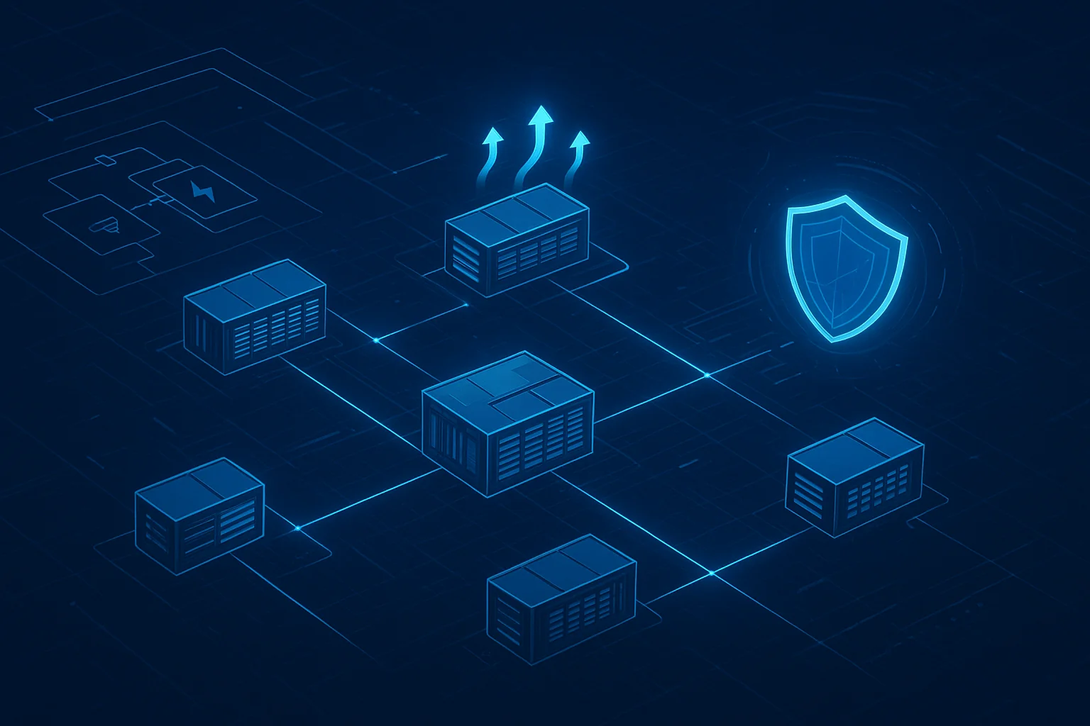
Strategy 1: Reduce blast radius with decentralization and modular architecture
If your continuity plan depends on one hyperscale building, you’re betting that:
the building remains physically accessible,
the critical spares you need are available,
and the utility and logistics environment is stable enough to rebuild quickly.
Recent global supply chain disruptions broke that assumption. Even without a direct physical incident, lead times for transformers, switchgear, and large-format cooling equipment can stretch into quarters — which turns “recover” into “wait.”
A decision framework for decentralization
Decentralization is not “go fully distributed.” It’s choosing where to place independent capacity so a single event can’t take out your whole service.
Use this simple decision matrix to evaluate your architecture:
Design choice | Improves | Adds complexity | Best when |
|---|---|---|---|
Single mega site | Operational simplicity | Extreme blast radius | Latency constraints + low physical risk |
Two sites in-region | Regional survivability | Replication + traffic management | You can tolerate regional fiber / latency differences |
Multi-site + edge nodes | Fast local recovery | More operational surfaces | You need continuity under localized disruption |
What modular infrastructure changes
Modular architecture changes the unit of deployment from “a building project” to “a repeatable block.” That matters when you need:
predictable commissioning and acceptance tests,
standardized spares,
and the ability to add or replace capacity in weeks rather than quarters.
For example, a prefabricated modular system like MetaRow Modular Data Center integrates cabinets, power distribution, cooling, and monitoring in a standardized design intended for rapid deployment and modular expansion.
For rapid redeployable capacity (backup nodes, temporary recovery clusters, or constrained sites), containerized approaches such as MetaCuber Container Data Center emphasize integrated subsystems and transportability.
Practical checklist: “Decentralize without creating chaos”
Define your maximum acceptable failure domain (rack row / room / building / campus).
Standardize a reference design (power path, cooling method, monitoring, security controls).
Decide replication boundaries: what fails over within a site vs across sites.
Pre-approve procurement alternates (equivalent components) for constrained supply environments.
Create an “add capacity” runbook: prerequisites, acceptance tests, and rollback steps.
⚠️ Warning: Decentralization without standardization often fails. You don’t get resilience — you get a bespoke fleet that is hard to maintain under pressure.
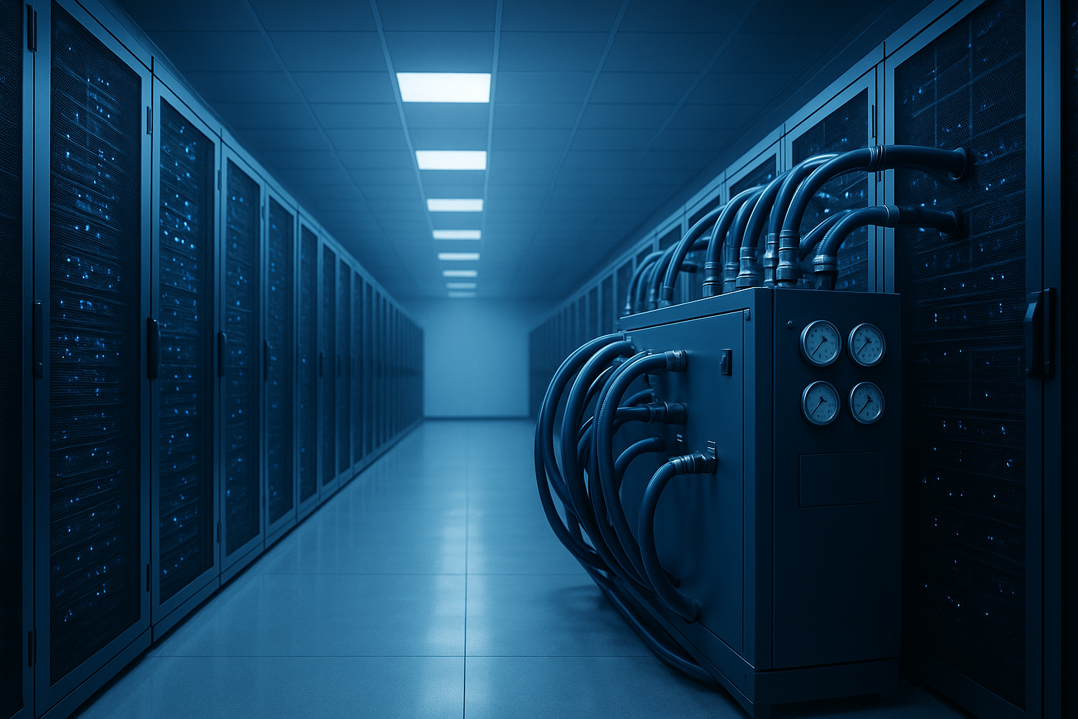
Strategy 2: Treat power continuity as a lifeline during grid failure
This is where data center power redundancy (UPS) design becomes a business-continuity requirement, not an electrical preference.
In many physical disruption scenarios, the first systemic impact isn’t the server room — it’s the grid.
A robust design assumes:
utility can disappear instantly,
generators might start successfully but not immediately,
and fuel logistics can be constrained.
Microsoft’s own datacenter guidance describes “dedicated 24×7 uninterruptible power supplies (UPSs) and emergency power support, which includes on-site generators” as part of sustaining availability under power events (Microsoft: Datacenter architecture and infrastructure).
The bridge problem: the seconds that decide the incident
The critical gap is the bridge window between utility loss and stable generator output — the “grid failure data center UPS generator bridge” problem your BCP ultimately lives or dies on.
That bridge is where:
servers crash or corrupt transactions,
cooling stalls,
and recovery turns into an outage.
Design the bridge explicitly:
define required ride-through time (based on generator start + transfer + stabilization),
validate it at full load (not lab load),
and ensure the power path remains maintainable.
Redundancy language you can defend in audits
When you need a vocabulary that maps to risk discussions, Tier definitions help.
Uptime Institute describes a Tier III data center as “concurrently maintainable with redundant components… with redundant distribution paths,” while Tier IV adds fault tolerance with “independent and physically isolated systems” so IT operations “will not be affected” by equipment failure or distribution interruption (Uptime Institute Tier Classification System).
You may not be building a certified Tier site — but you can use the same redundancy logic to justify your power topology choices.
Where modular UPS fits (without over-claiming)
A modular UPS strategy is often chosen in environments where:
growth is staged,
maintenance windows are tight,
and you need a path to N+1 without a full rip-and-replace.
If you’re evaluating options, the UPS Power System category provides examples of rack and tower UPS families you can align to your required ride-through and redundancy design.
Validation questions (use these in your RFP):
What is the ride-through time at 100% load with your battery design assumptions?
How is redundancy implemented in the distribution path (not just in UPS capacity)?
What’s the maintenance procedure — and what remains protected during maintenance?
How is generator compatibility tested (not just specified)?
Strategy 3: Prevent secondary damage with thermal control and isolation
In physical incidents, the most expensive damage is often secondary — a practical shorthand is secondary damage control (fire, water, dust):
smoke infiltration,
water from suppression,
dust and debris,
and thermal runaway when airflow and cooling paths are disrupted.
This is where “resilience” becomes a facilities-and-IT integration problem.
Design for containment and controllable failure domains
A resilient thermal design has two goals:
Maintain safe operating temperatures for unaffected zones.
Limit exposure of critical IT nodes to contaminated air or water.
Containment is one of the simplest controllable levers. In modular designs, hot/cold aisle containment and airflow management can be integrated as part of the build system rather than retrofitted later.
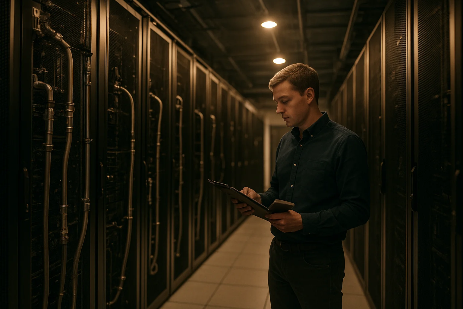
Monitoring is the trigger, not the dashboard
DCIM is often treated as reporting. In resilience scenarios, it’s a trigger layer:
detect abnormal temperature gradients,
detect smoke/humidity spikes,
identify which aisle or module is impacted,
and isolate the failure domain before the event cascades.
(When you assess DCIM, focus on alarm fidelity, escalation workflows, and what it can control, not just what it can display.)
Hardened micro-modules for harsh environments
For edge and constrained sites, enclosure hardening can materially reduce secondary damage. In practice, many teams treat micro data center IP55 enclosures as part of their “keep core nodes alive” strategy when the surrounding environment is unpredictable.
For instance, Coolnet’s MetaRack is referenced in an edge deployment context with “military-grade protection (IP55)” and a vibration-resistant design (Edge Computing Nodes: Micro Data Center Solutions). That kind of protection rating can be relevant when your risk model includes dust, water spray, or harsh outdoor proximity — and when rapid replacement is part of the recovery plan.
Pro Tip: In your BCP, document not only how you keep systems running — but also how you re-enter the site safely (access control, escorts, isolation steps) and how you prevent well-intended recovery actions from causing water or dust damage.
A practical “kinetic resilience data center” readiness checklist (BCP-facing)
Use this as an executive- and tenant-readable appendix.
1) Failure domain definition
Do you have a documented maximum blast radius (room/building/campus)?
Are critical services deployed across independent failure domains?
2) Power continuity validation
Is the utility-to-generator bridge time defined and tested at full load?
Do you have a maintainable power path (no single maintenance action causes downtime)?
3) Thermal and secondary damage control
Can you isolate an aisle/module quickly based on sensors?
Are suppression and water ingress risks explicitly addressed?
4) Recovery under supply chain constraints
Do you have approved alternates and a spares strategy?
Can you deploy a standardized capacity block without waiting for bespoke design work?
5) Evidence and auditability
Do you have commissioning/acceptance test records you can show tenants?
Are your resilience claims tied to a standard (Tier logic, zone separation principle, internal test protocols)?
Agility is the ultimate armor
You can’t predict which physical event will happen — but you can control how large the failure domain is, whether power and cooling survive the first minutes, and whether recovery is a documented, repeatable process.
The common thread across decentralization, redundancy, and secondary-damage control is agility: building with standardized modules, validating lifelines, and designing for isolation.
Next step: resilience assessment
If you want a technical review of your current failure domains and recovery plan — including modular options for distributed capacity — contact Coolnetpower to request an assessment.