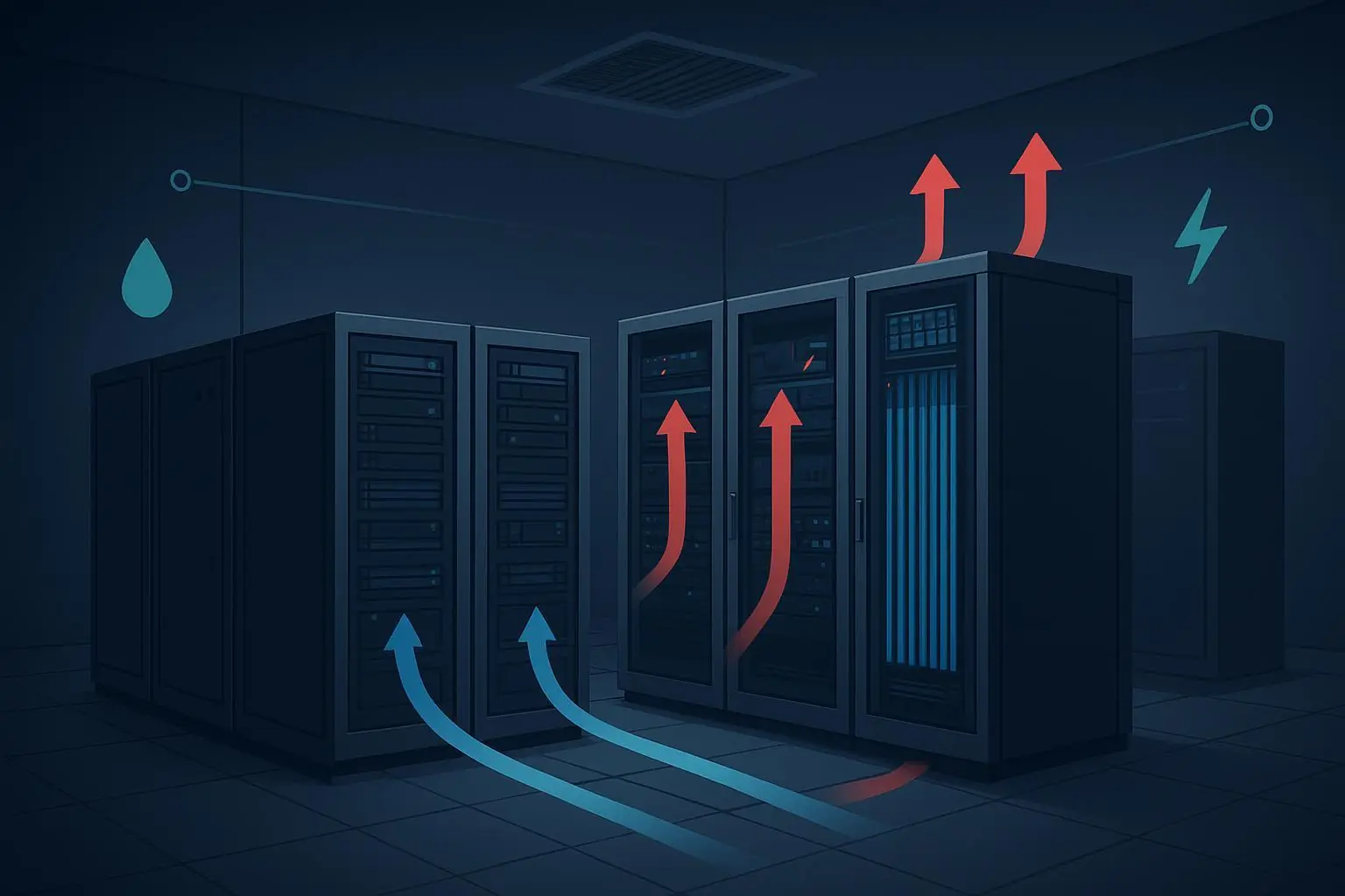
If you’re trying to raise rack density without expanding floor space, here’s the deal: the clearest trigger to consider direct-to-chip (D2C) liquid cooling in the 20–40 kW band is a space density bottleneck. At these loads, airflow, fan power, and aisle containment start to work against you. D2C lets you move most heat with liquid inside the rack, stabilizing thermals and freeing headroom for more compute within the same footprint—especially in edge and micro data centers where site and power are both tight.
Key takeaways
Primary threshold: When footprint is fixed and you must increase compute density, D2C in the 20–40 kW range often becomes the practical next step. Secondary triggers include rising fan power/PUE drift and compliance goals (PUE/WUE/EED) that air-only can’t meet in your current envelope.
Best-fit scenario: Edge/micro data centers benefit from compact liquid-to-liquid CDUs, warm-water operation aligned to W-classes, and short hose runs. Hybrid zones (air + selective D2C) ease migration.
What you need: A CDU boundary to keep facility water out of IT racks, rack manifolds with dropless quick-disconnects, sensors (T/flow/ΔP) and layered leak detection tied into BMS/DCIM.
Use our one-page evaluation pack in this guide: a readiness Go/No-Go checklist, editable BOM templates with capacity math, and a commissioning & leak-test plan.
Is 20–40 kW the tipping point for direct-to-chip?
There isn’t a single standard that mandates “go liquid” at 20–40 kW per rack. Instead, use decision triggers:
Space density bottleneck (primary). If floor area is capped but compute demand isn’t, selective D2C cold plates can lift per-rack power while reducing reliance on high-pressure airflow. Industry analyses point to liquid cooling as the path to higher densities with better thermal control as chips scale up in power. See the adoption discussions in DataCenterDynamics and DataCenterKnowledge for context on density trends and operational benefits: according to the DCD perspective on direct-to-chip trajectories, D2C is enabling higher-density builds; DCK likewise outlines how liquid cooling supports future, denser data centers (DCD commentary on D2C density trajectories; DCK on liquid cooling supporting denser data centers).
Rising fan power and PUE drift. As rack power climbs, fan energy grows fast and starts to dominate cooling overheads. Demonstration work from a public agency shows how moving heat via liquid reduces the fan burden and improves overall efficiency at higher densities, even though no single breakpoint is prescribed (California Energy Commission demonstration on low-cost liquid cooling, 2024).
Compliance constraints. Warm-water operation (aligned to W-classes) paired with dry coolers or heat reuse can help reduce chiller runtime and water consumption, supporting energy/water targets where air-only struggles at higher densities. OCP’s Advanced Cooling Solutions materials explicitly align with ASHRAE TC 9.9 cooling environments (OCP cooling environments and ASHRAE TC 9.9 alignment, 2024).
Tip: At 20–40 kW, selective D2C (CPU/GPU on plates, residual air for the rest) often delivers the best first step, while keeping an option to progress to fuller liquid coverage if needed.
Edge/micro‑DC deployment paths: reuse what you can, isolate what you must
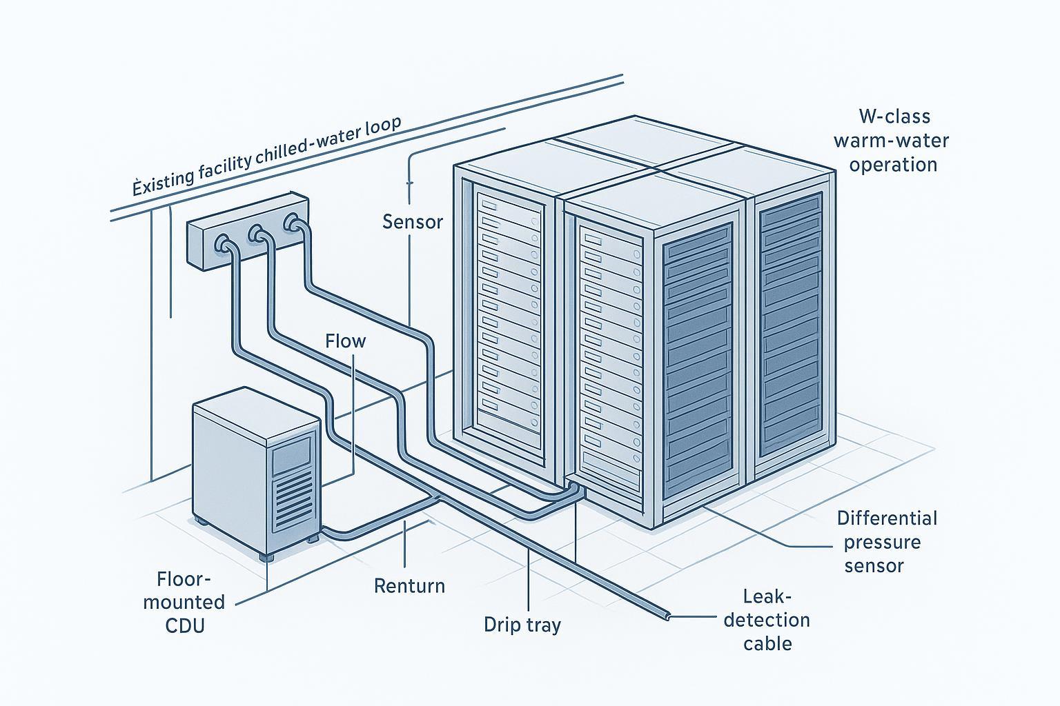
In edge and micro sites, space and power are scarce. That’s why a liquid-to-liquid coolant distribution unit (CDU) is your friend: it forms the boundary between the facility water system (FWS, e.g., existing chilled water/CRAH loops) and the technology cooling system (TCS) that feeds the cold plates. You keep facility water out of IT racks and control the TCS independently.
Retrofit via existing CHW/CRAH. Tie an L–L CDU into the chilled-water supply/return you already have. Validate hydraulic capacity, water chemistry, and materials compatibility. Confirm UPS coverage for TCS pumps/controls.
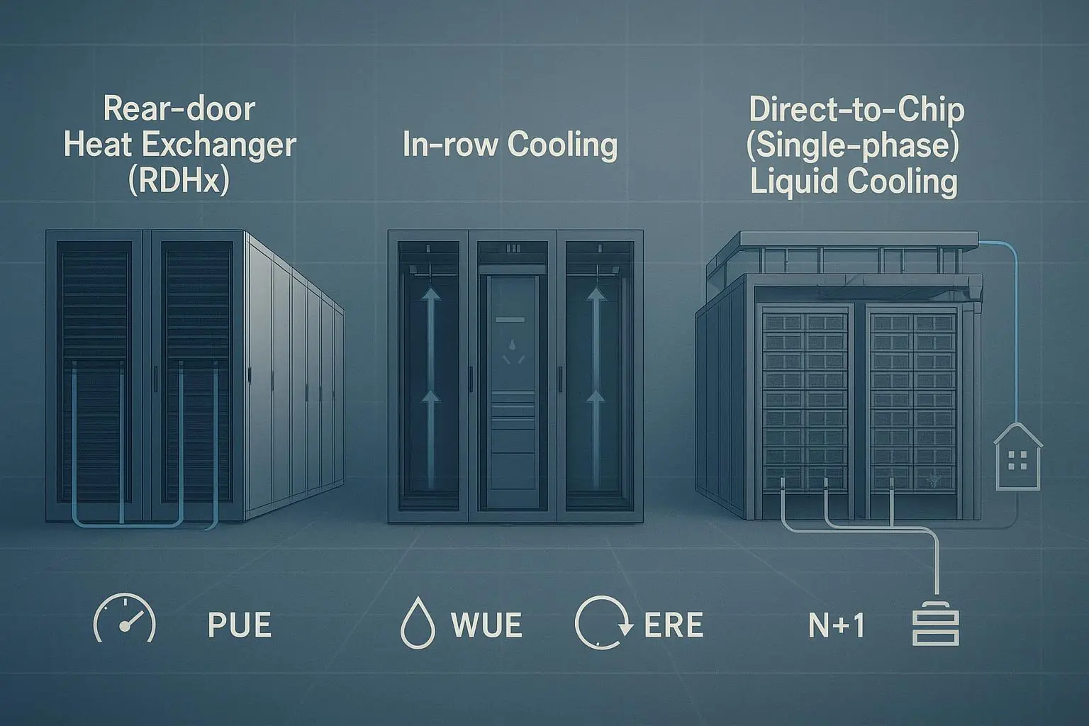
Hybrid zones. Start with selective D2C in the highest-density racks and retain air/RDHx for others. This staged approach can help you hit density goals without a full-floor overhaul. For a primer on hybrid paths and W‑class warm‑water concepts, see this neutral overview on scaling AI cooling with hybrid zones (hybrid paths and W‑class primer).
Warm-water viability. ASHRAE’s W‑classes provide the facility-side temperature envelope; warmer classes (e.g., W32/W45) can enable chiller‑lite or chiller‑free operation in suitable climates when paired with appropriate TCS setpoints. For a concise context on W‑class usage across multi‑cooling environments, see ASHRAE Journal’s podcast overview (ASHRAE Journal podcast on multi‑cooling environments and W‑classes, 2026).
Readiness triage: Go/No‑Go checklist
Use this quick self‑assessment before detailed engineering. If two or more items are “No,” pause for mitigation planning.
Space and density
Is your footprint fixed with a clear need to raise compute density now?
Can selective D2C get you to the target kW/rack without adding rows?
Electrical readiness
Do you have headroom for CDU pumps/controls? Are they on UPS?
Do panelboards/breakers support the added loads and control wiring?
Mechanical and facility interface
Is there an accessible CHW/CRAH tie‑in point near the target pod?
Is there floor or in‑row space for the CDU with service clearances?
Is hose routing feasible with proper bend radius and QD access?
Water quality and materials
Is FWS chemistry documented? Do you have a TCS filtration plan (<25 µm) and conductivity/pH targets?
Are wetted materials compatible across CDU/manifolds/hoses/plates?
Operations and safety
Are BMS/DCIM points available for T/flow/ΔP/leak, with alarm playbooks?
Do staff have maintenance and leak‑response procedures?
Do you have a commissioning script with acceptance criteria and re‑test cadence?
If you answered “Yes” across these categories, proceed to detailed design and BOM.
Component primer: CDUs, manifolds, QDs/hoses, sensors and monitoring
CDUs (liquid-to-liquid)
Role: Provide FWS↔TCS isolation via a plate heat exchanger; variable‑speed pumps sized to meet differential pressure and flow; filtration; buffer/expansion; fluid quality monitoring; and controls with BMS/DCIM integration. Industry coverage describes capacities from rack‑mount tens of kW to multi‑MW floor units (overview of CDUs as the heart of a DLC system).
W‑class context: Facility water supply aligned to W‑classes (e.g., W27/W32/W45) sets the upstream envelope; the TCS setpoints to the cold plates are controlled by the CDU. For a shared terminology reference, see the OCP–ASHRAE alignment deck (OCP cooling environments deck, 2024).
Manifolds and distribution
Provide rack‑level distribution with isolation and balancing valves. Plan service loops, respect hose bend radii, and add clear labeling. Place drip trays under manifold banks in micro sites and ensure access for QD operations. Industry whitepapers highlight the importance of filtration and accessible service points for maintainability (DCD whitepaper on DLC system challenges, 2025).
Quick‑disconnects and hoses
Select dropless QDs with appropriate pressure rating and seal materials. Size hose ID/OD for design flows; include brackets/clamps to prevent strain. Route for visibility and leak‑sensor coverage. These practices limit spill volume and speed maintenance (see DCD challenges whitepaper above).
Sensors, monitoring, and alarms
Temperature at CDU supply/return and rack manifolds; component sensors where supported.
Flow meters per loop or per rack to verify distribution; differential pressure across branch circuits to catch blockages or micro‑leaks.
Layered leak detection: cable sensors along manifolds and piping runs; spot sensors in drip pans and CDU base; monitor buffer tank levels and flow/pressure deltas. TI’s application note provides concrete signal strategies for leak, flow, and pressure monitoring in liquid‑cooled servers and CDUs (TI note on leak/flow/pressure monitoring, 2024).
Integration: Map CDU and rack sensor I/O into BMS/DCIM with alarm tiers (warning → automated interlocks). For an example of telemetry aggregation concepts, see this DCIM page as a neutral reference (BMS/DCIM integration concept example).
BOM templates and capacity sizing math
Use these vendor‑agnostic templates as a starting point and adapt to your project.
CDU
Plate heat exchanger: specify approach temperature; verify compatibility with fluids.
Pumps: size for required flow and total dynamic head (sum of component ΔP plus margin); consider N+1 redundancy.
Filtration: ≤25 µm with differential pressure gauge; stock spare cartridges.
Instrumentation: T (supply/return), flow, ΔP, conductivity/particle sensors; I/O for BMS/DCIM.
Power: dedicated feeds; UPS coverage for pumps/controls; E‑stop and isolation valves.
Manifolds
Supply/return headers with isolation and balancing; labeled take‑offs; drip tray with drain or absorbent; mounting hardware and service clearances.
Quick‑disconnects and hoses
QD type/size, pressure rating, seal material; hose ID/OD and bend radius; brackets/clamps; service loops; protective sleeves.
Sensors and leak detection
Temperature probes; flow meters; ΔP sensors; leak cable and spot sensors; level sensors; gateways for BMS integration; alarm logic documentation.
Containment and spares
Drip trays/catch pans; absorbents; signage; commissioning spares (hoses/QDs/seals); flushing rig and filters.
Capacity math (single‑phase water; project‑specific, validate with vendor curves):
Heat balance: Q = m·Cp·ΔT. For water, Cp ≈ 4.186 kJ/kg·K.
Rule of thumb flow per heat load at ΔT = 10 K: approximately 2.6 L/min per kW. Example: a 30 kW rack → ~78 L/min across cold‑plate circuits; scale with ΔT and component ΔP, and verify per‑branch flows.
Pump head: sum of plate, hoses, QDs, cold‑plate channels, and manifold losses with a design margin; confirm operating point on the pump curve with N+1 as required.
Retrofit risk register and commissioning/leak‑test plan
Track the top risks early and bind them to mitigations and tests.
Common retrofit risks and mitigations
Long‑lead facility tie‑ins or transformer delays → stage deployment with temporary dry coolers; schedule CDU delivery to align with outages.
Materials incompatibility or poor water quality → specify TCS chemistry, cleanliness, and filtration; verify with pre‑install sampling.
Service access constraints in micro sites → choose compact CDUs, wall‑mounted manifolds, and plan hose routing and QD access up front.
Alarm fatigue or missing interlocks → tiered alarms and clear playbooks; simulate faults during commissioning.
Commissioning and acceptance testing
Pre‑install verification: visual/materials checks; pressure‑decay on segments with recorded acceptance; flushing and filtration run.
Leak‑test methods: tracer‑gas (helium/hydrogen) for high‑sensitivity component and assembly tests; avoid water‑bath methods that can mask micro‑leaks. For method details and calculating leak rate from pressure drops, see engineering guidance from ATEQ (best practices for leak testing in cooling components).
Functional tests: balance flows to design tolerance (e.g., ±5–10%); calibrate sensors; validate alarm thresholds and automated responses (valve close/pump stop); perform CDU pump failover; run a 24–72 hour thermal soak at target load.
Records and re‑test cadence: document acceptance criteria for leak rates and steady‑state T/flow/ΔP; schedule re‑tests after maintenance windows.
Micro example: edge pod at 15–30 kW/rack (vendor‑agnostic workflow)
One 3–6 rack edge pod targets 20–30 kW per rack. The facility has CHW nearby but limited space and power.
Place a compact liquid‑to‑liquid CDU in‑row next to the pod; tie into CHW for the FWS side.
Mount a supply/return manifold on a side wall with labeled take‑offs and a drip tray; route short hose sets to each rack; use dropless QDs at server inlets/outlets for serviceability.
Add leak‑detection cable along the manifold base and spot sensors in trays and in the CDU base. Instrument supply/return T, per‑loop flow, and ΔP; integrate points into BMS/DCIM with tiered alarms and safe‑shutdown interlocks.
Operate the facility side at a warm W‑class where climate allows, while the CDU controls TCS inlet to the cold plates.
In similar edge builds, prefabricated micro‑modules and CDUs can be used to accelerate deployment without custom civil works. For example, Coolnet can be used to supply prefabricated micro‑modules and CDUs for 15–30 kW/rack expansion with warm‑water loops; see this neutral explainer on modular suitability for micro sites (modular micro‑DC suitability overview).
Standards and sources to consult
For W‑classes and multi‑cooling environments context, review the ASHRAE Journal’s coverage and OCP alignment: see the multi‑cooling environments podcast and OCP deck (ASHRAE Journal podcast on W‑class usage, 2026; OCP cooling environments and ASHRAE TC 9.9 alignment, 2024). Formal W‑class tables are in ASHRAE publications.
For adoption context and density/efficiency narratives, see independent industry coverage (DCD commentary on D2C density trajectories; DCK on liquid cooling and denser data centers).
For retrofit demonstrations and energy impacts, consult the California Energy Commission’s 2024 report (CEC liquid cooling demonstration).
For leak sensing/monitoring schemes and instrumentation, see TI’s application note (leak/flow/pressure monitoring strategies). For leak‑testing methods and acceptance guidance, see ATEQ’s engineering notes (data‑center cooling component leak‑testing best practices).
Next steps: get the one‑page evaluation pack
Download the one‑page evaluation pack from this guide: a readiness Go/No‑Go checklist, editable BOM templates (with sizing math), and a commissioning & leak‑test plan you can adapt to your site. If you need neutral templates or tools, Coolnet can be used as a resource for standardized checklists and micro‑site planning aids.