Integrating AI controls with liquid cooling and DCIM isn’t a single “integration project.” It’s a set of contracts across three operational worlds that usually have different owners, networks, and failure modes:
Facilities controls (BMS/OT): keeps the plant stable and safe.
IT visibility (DCIM/IT): understands workloads, capacity, and what’s happening rack by rack.
Liquid cooling loops (DLC/CDU/rear-door): add sensors, alarms, and interlocks that can’t be treated like “just another HVAC point.”
This guide is written for enterprise teams at the consideration stage: you’re evaluating options and want a blueprint that’s vendor-neutral, rollback-capable, and safe to operate.
Key Takeaway: If you can’t clearly answer “who owns the setpoint?” for every critical variable (supply temp, flow, pump enable, valve position), you don’t have an integration yet—you have a dashboard.
Table of Contents
ToggleWhat you’re actually integrating (and where projects go wrong)
At a high level, most deployments look like this:
Field devices (sensors, valves, pumps, meters)
Local controllers (PLC/DDC) that keep the loop stable
BMS (often BACnet-oriented) supervising the building plant
DCIM aggregating facility + IT telemetry for operations and capacity
Supervisory AI providing optimization recommendations or write-back control
The failure patterns repeat across sites:
Telemetry without ownership: Everyone can see a number, nobody can explain what it means or who changes it.
Writes without guardrails: A “smart” system is allowed to write setpoints without constraints, audit trails, or an easy release mechanism.
Liquid cooling treated like air cooling: Teams skip dew point/condensation risk, leak response, and rack-level interlocks.
To avoid those traps, design around three data planes:
Telemetry (what’s the current state?)
Events/alarms (what’s abnormal, and how urgent is it?)
Commands (what can we change, under what rules?)
Step 0: prerequisites and starting state
This guide assumes you’re building supervisory controls. It does not replace OEM safety logic or local plant protection. Your target architecture should always tolerate losing the AI layer without losing safe operation.
Minimum prerequisites checklist
Before you choose tools or vendors, confirm these basics:
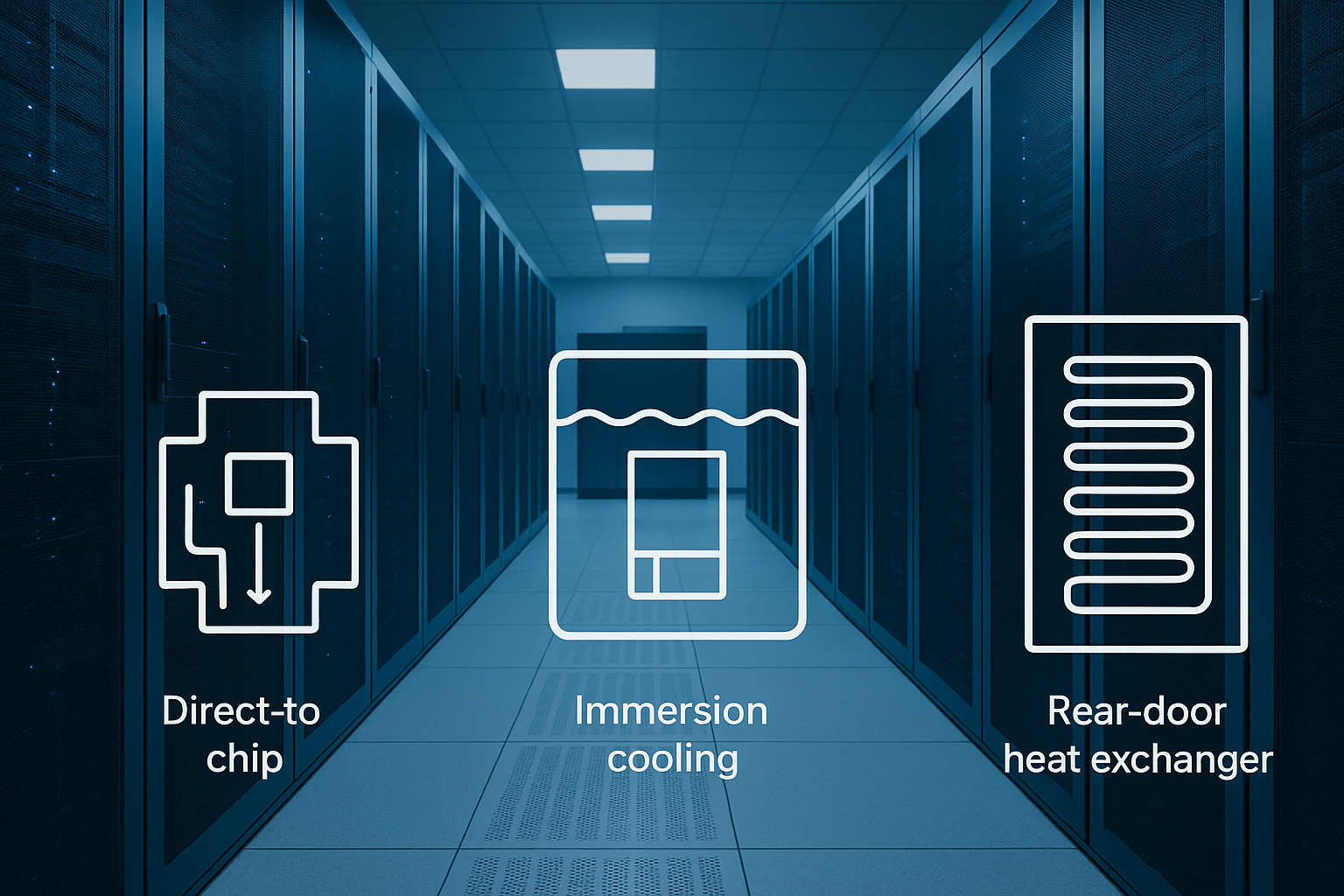
You have a known liquid cooling topology (direct liquid cooling / direct-to-chip, CDU, rear-door, immersion where relevant).
OT and IT teams agree on network zones, ownership, and remote access rules.
You have a change control process—even lightweight—covering configuration versioning and approvals.
You’ve defined baseline operating targets and constraints (temperature bands, minimum flows, maximum ramp rates, alarm thresholds).
If you need a quick way to baseline sizing assumptions and start a capacity conversation, a cooling and power sizing calculator can help frame the first iteration—treat it as a starting point, not a final design. Here’s a data center cooling capacity calculator that’s explicitly positioned as a preliminary estimate.
Starting-state definition (write it down)
Document these “starting state” items in a one-page integration brief:
What systems exist today (BMS vendor, DCIM vendor, controllers, CDUs, sensors)?
What’s already integrated (if anything) and at what fidelity (points only vs alarms vs writes)?
What you will not automate in v1 (e.g., plant-level chiller sequencing, emergency shutdown logic).
Step 1: choose your deployment architecture (edge vs cloud)
The edge-vs-cloud question becomes simpler when you separate control from analytics.
Control loops (or anything that behaves like a control loop) want low latency, high availability, and local autonomy.
Fleet analytics (trend analysis, reporting, cross-site benchmarking, model training/retraining) can benefit from cloud scale.
A practical enterprise pattern is hybrid:
Edge runs:
real-time data normalization
local inference (if you use ML in the loop)
guardrails and rate limits
local “safe mode” behavior during network or platform outages
Cloud / central runs:
long-horizon optimization
cross-site baselining
model training, validation, approvals, and deployment orchestration
What edge is protecting you from
In a critical facility, the risk isn’t just latency. It’s also:
intermittent connectivity between sites and central systems
data sovereignty constraints (what can’t leave the site)
failures that should degrade gracefully (AI offline → deterministic control, not chaos)
Verify your architecture before you buy anything
Write a short checklist and validate it with OT/IT/security:
Can the site operate safely if cloud connectivity drops?
Are the minimum safety-related points available locally with correct units and timestamps?
Is there an explicit “manual takeover” and “relinquish control” mechanism?
(If you’re documenting this section for procurement, this is where the phrase edge vs cloud AI controls for data center cooling should show up in your evaluation criteria—because it’s not a preference, it’s an uptime and governance decision.)
Step 2: map protocols to responsibilities (BACnet, Modbus, OPC UA)
Most data center integrations are not “one protocol.” They’re a mix.
A useful mental model is:
BACnet for building/HVAC objects and supervisory overrides
Modbus for meters and device registers (often inside the plant or CDU ecosystem)
OPC UA for structured data modeling, events, and secure OT/IT bridging
If you’re scanning vendor documentation, the shorthand you’ll often see is BACnet Modbus OPC UA integration—but what matters is which layer is allowed to read, write, and alarm on each point.
BACnet: objects, priorities, and safe relinquish
BACnet’s command behavior matters because it offers a practical safety primitive: the priority array. Chipkin’s overview of BACnet priority arrays explains how a commandable point can hold up to 16 priority slots, where the active value is the highest-priority non-null entry.
In integration terms, this enables a pattern you want in any supervisory AI write-back system:
Human/operator and safety logic sit at higher priorities.
Supervisory optimization writes at a lower priority.
“Rollback” can be as simple as writing NULL (relinquishing) at the AI priority—immediately returning authority to the underlying automation.
This isn’t a reason to write freely. It’s a reason to design deliberate priority strategy from day one.
Modbus: common, simple, and insecure by default
Modbus is everywhere because it’s easy to implement and widely supported. It’s also not designed for today’s security expectations.
Real Time Automation bluntly notes that Modbus has no built‑in security. In practice: if you can reach the device, you can often read and potentially write.
For enterprise deployments, the right response isn’t panic—it’s architecture:
isolate Modbus networks into OT zones
allowlist which systems can talk to which devices
prefer read-only where possible
if remote transport is unavoidable, wrap or tunnel close to the edge
For a practical mitigation discussion, Trout outlines approaches for how to secure Modbus TCP in OT networks (segmentation, allowlisting, monitoring, and secure transport patterns).
OPC UA: model the data and secure the bridge
If you’re bridging OT into IT/DCIM and you need security and structure, OPC UA is often the “bridge layer.”
Two specifics matter for enterprise rollouts:
Security mode: the OPC Foundation notes that OPC UA security mode should be configured as “Sign” or “SignAndEncrypt” (not “None”) in real deployments.
Certificate lifecycle: certificate trust, revocation, and rotation are part of the operating model; see the OPC Foundation’s OPC UA certificate management reference.
The gateway pattern (what to normalize)
Most enterprise programs eventually converge on a gateway/normalization layer that:
maps registers/objects into a consistent tag naming convention
normalizes units and scaling
enforces read/write permissions by point type
publishes events with clear severities
Your goal isn’t “support all protocols.” It’s “present one coherent, governed data contract upward.”
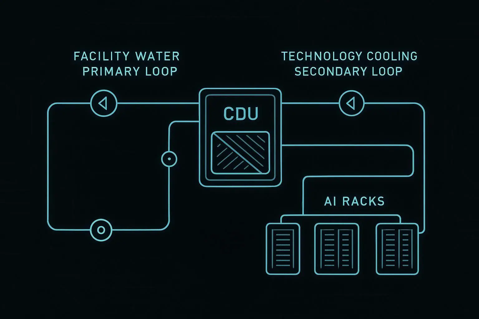
Step 3: model the liquid cooling handoffs (DLC/CDU/L2R)
Liquid cooling becomes manageable when you treat the system as handoffs between loops, not a single monolithic pipe.
A typical pattern:
Facility loop: chilled water / heat rejection infrastructure.
CDU loop: isolates and controls coolant delivered to IT equipment.
Rack loop: distributes coolant to cold plates or rear-door coils.
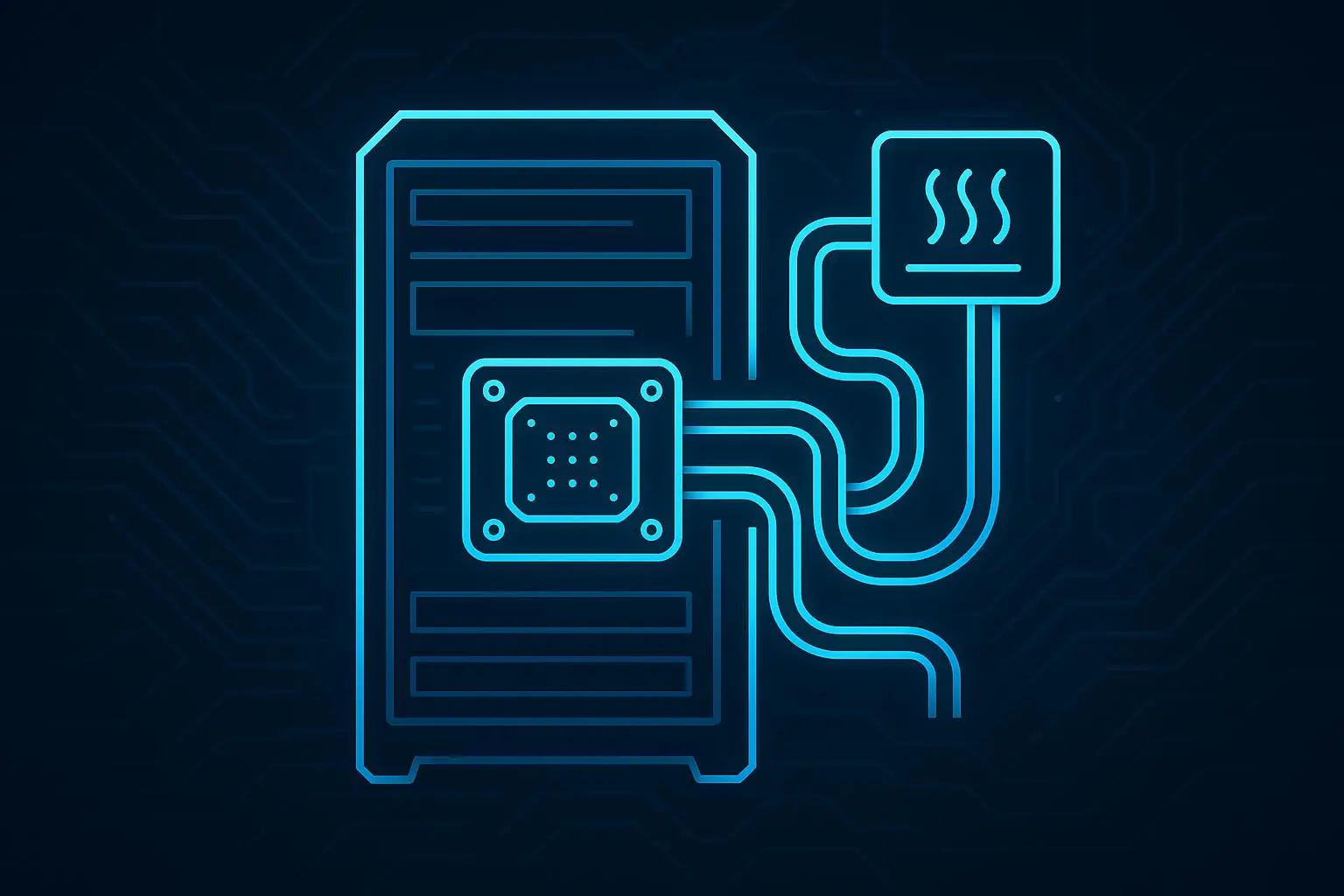
DLC (direct liquid cooling / direct-to-chip): what changes
DLC increases heat removal capacity at the rack, but it also increases the cost of misconfiguration.
The integration implications:
flow and pressure become first-class control variables
dew point and condensation risk must be monitored and constrained
leak detection and isolation behavior need defined escalation paths
CDU: your integration “choke point”
CDUs are often where you can standardize telemetry and control, even when downstream racks vary.
When you evaluate CDU integration, insist on clear answers to:
What telemetry is available (flow, supply/return temperatures, delta-T, pump status, alarm codes)?
Is the interface read-only or read/write—and what’s the access model?
How are alarms exposed (polled registers vs evented alarms)?
For procurement and internal documentation, it can help to anchor CDU terminology to a specific product class reference, such as Coolant Distribution Units (CDU).
(If your controls team is formalizing requirements, this is also where the phrase coolant distribution unit monitoring Modbus usually becomes concrete: which CDU points are mapped to which registers/objects, at what update rates, and with what write restrictions.)
L2R / rear-door heat exchangers: scope and handoffs
Rear-door heat exchangers change the rack’s relationship to the room:
you may still have air handling for non-liquid-cooled components
rack-level performance is tied to door coil flow and inlet water temperature
alarms often include fan behavior and coil delta-T patterns
As a concrete reference point for that device class, see a rear-door HX example like Chilled Water Rear Door Heat Exchanger.
Immersion: treat it as a different operational model
Immersion introduces different maintenance routines and different telemetry emphases. If your program includes immersion, handle it as its own integration track.
For a device-class reference, Immersion liquid cooling can anchor what you mean by “immersion” in procurement and internal documentation.
Verification checkpoint: define ownership boundaries
Create a one-page RACI that answers:
Who owns supply temperature setpoints for each loop?
Who owns pump enable/disable logic?
Who acknowledges/clears alarms?
Under what conditions does IT load need to be throttled or migrated?
If those answers are unclear, pause. It’s cheaper than “integrating your way into an outage.”
Step 4: build your point list and data contract for DCIM integration for liquid cooling
Most integration failures are not protocol failures. They’re data contract failures: wrong units, mismatched timestamps, points that mean different things across sites, or alarms that aren’t actionable.
A minimum viable point list (example)
This is a vendor-neutral starting template. Treat it as a baseline and extend per device/OEM.
For each CDU:
Supply temperature (°C)
Return temperature (°C)
Delta‑T (°C)
Flow rate
Supply pressure / differential pressure
Pump status (per pump)
Valve position (if applicable)
Leak detection status
Alarm summary + alarm code
Controller mode (auto/manual/service)
For each liquid-cooled rack/pod (if available):
Manifold supply/return temps
Rack-level flow
Leak detection
“Flow proven” interlock status
For each zone (BMS/DCIM side):
Room temperature and humidity
Dew point (or inputs to compute it)
Air assist metrics (fan wall / CRAH supply, where applicable)
The data contract fields you should require
For every point you ingest into DCIM and AI layers, define:
Name (consistent naming convention)
Unit (and scaling rule)
Update rate (poll interval or subscription)
Quality flag (good/stale/invalid)
Source of truth (which system is authoritative)
Write permissions (none/read-only or controlled write with constraints)
Pro Tip: Add an “owner” metadata tag to points (Facilities, Controls, DCIM, IT). It prevents silent drift where teams assume someone else owns the change.
Step 5: design write safety, guardrails, and rollback
“AI controls” becomes operationally acceptable when it’s hard to do something dangerous—and easy to go back.
BACnet write safety: pick a priority strategy
If you use BACnet writes, you need a documented priority strategy, such as:
Emergency and life safety override priorities reserved for safety logic.
Operator manual override priority reserved for humans.
Supervisory optimization priority deliberately lower.
Then define your rollback behavior:
when optimization is disabled, the AI layer relinquishes (writes NULL at its priority)
when comms health is degraded, freeze or revert to last-known-safe state
Command constraints: bounds, rate limits, and setpoint freezing
Regardless of protocol, enforce constraints at the write boundary:
hard bounds (min/max setpoints)
ramp rate limits (how fast values can change)
hysteresis to avoid oscillation
minimum dwell time before another change
Safety interlocks: flow-verification before enabling load
At a minimum, define interlocks so that:
high-density IT load isn’t enabled unless coolant flow is verified
certain alarms (leak detection, pump failure without redundancy) trigger controlled escalation
Rollback mechanisms (controls)
Rollback isn’t a single switch. It’s a set of mechanisms:
configuration versioning: every gateway map and control rule set is versioned
canary rollout: start with one pod/row before fleet-wide enablement
safe mode: pre-defined conservative setpoints and no write-back
audit trail: who changed what, when, and why
If you’re building evaluation criteria, explicitly require change control rollback for building automation (not just “backups”)—including who approves changes and how long rollback takes.
Rollback mechanisms (AI/ML)
If you use ML models in advisory or closed-loop control, add MLOps-style safety:
model versioning and approval gates
“shadow mode” (predict without writing) for validation
confidence thresholds (below threshold → no write)
drift detection and retraining triggers
clear fallback behavior (deterministic control policy when ML is disabled)
⚠️ Warning: Never let a supervisory AI layer bypass OEM protections or local safety logic. Your design goal is “AI improves efficiency,” not “AI is the last line of defense.”
Step 6: commission in stages (with acceptance tests)
A safe commissioning plan usually progresses through four stages:
Observe: read-only telemetry, validate units and timestamps
Advise: recommendations only, no write-back
Write-limited: constrained writes (low priority, strict bounds)
Closed-loop: only when acceptance tests pass and rollback is proven
Acceptance tests you should run
Build a test matrix that covers normal and failure conditions:
comms loss between layers (edge to cloud; gateway to BMS/DCIM)
sensor failures (stuck values, out-of-range, time drift)
pump failover and redundancy behavior
leak detection events and escalation flow
manual override conflicts (human takes control; AI must relinquish cleanly)
Cyber checks that must be part of commissioning
Treat protocol reality seriously:
validate OT/IT segmentation (no unexpected routing)
verify OPC UA certificate trust and rotation process
confirm Modbus TCP is not unintentionally exposed beyond intended zones
Step 7: operations and continuous improvement
Once live, the goal is boring stability with measurable improvement.
Separate what different roles need:
Operators: clear alarms, explicit “what to do now,” and safe mode visibility
Controls engineers: deeper telemetry, trend windows, point-quality flags, and configuration diffs
IT/security: access logs, certificate health, network changes
Define your post-change verification window:
after any control rule or model change, review a fixed time window of trends
confirm no new oscillations, no alarm spikes, and no setpoint “hunting”
Step 8: training paths and org readiness
Liquid cooling + DCIM + AI touches multiple teams. Training should be role-based.
Role-based training plan
Operators (shift staff):
what each major alarm means (low flow, high delta‑T, leak detection)
how to confirm system state in DCIM vs local HMI
how to put the system into safe mode and how to confirm it worked
Controls engineers / commissioning:
protocol mapping and point scaling validation
write priority strategy (BACnet) and controlled write policy
acceptance tests and regression testing after changes
IT/security:
network zoning, remote access, and monitoring
certificate lifecycle (OPC UA)
change control for gateways and edge runtime
Facilities management:
who owns which setpoints and what constitutes an “approved change”
maintenance workflow changes introduced by liquid cooling
Update your runbooks
At minimum, revise or create:
SOPs for alarm response
MOPs for planned changes
EOPs for leaks, comms failures, and thermal excursions
Procurement questions to bake into evaluations
When you evaluate AI control options and integration stacks, ask:
Do you support BACnet/Modbus/OPC UA in ways that match our control boundaries?
Can we run critical logic at the edge (local autonomy)?
How do you implement change control and rollback for configurations and models?
What training is included (operators vs engineers)?
FAQ
Can supervisory AI write setpoints directly?
It can, but it shouldn’t do so without constraints. If you allow write-back, enforce bounds, rate limits, approval gates, and a simple “relinquish control” mechanism. BACnet priority strategy can help, but governance matters more than protocol.
Do we need OPC UA if we already have BACnet?
Not always. OPC UA is most valuable when you need secure, modeled OT/IT bridging with events and certificate-based trust. If BACnet is sufficient within a controlled OT zone and you can enforce segmentation and governance, you may not need an additional layer.
How do we handle Modbus security on legacy CDUs?
Assume Modbus is insecure by default. Segment networks, allowlist endpoints, keep writes minimal, and wrap transport where needed. The key is enforcing security at the network and gateway layers.
What does “rollback” mean in a building controls context?
Rollback is the ability to return to a known-safe operating mode quickly. Practically, it includes: relinquishing overrides, reverting configuration versions, switching to safe-mode setpoints, and disabling AI write-back while maintaining deterministic control.
Next steps
If you’re evaluating solutions right now, the most useful next artifact is a commissioning-ready packet:
an integration point list template (telemetry + alarms + allowable writes)
an acceptance test matrix for staged commissioning
a rollback playbook (controls + ML)
Build those three documents first—then vendor selection becomes much less ambiguous.
Appendix — Coolnetpower reference integrations (neutral)
Coolnetpower publishes liquid cooling product categories that commonly appear in enterprise programs, including CDUs, rear-door heat exchangers, immersion solutions, and cold-plate/direct liquid cooling concepts. Their liquid cooling category page provides a consolidated reference list for these device classes.
In addition, Coolnetpower describes a broader “data center integrated solution” concept that combines power, cooling, security, and monitoring into a unified operational approach, and references “DCIM – Data Center Infrastructure Monitoring” as part of that framing.