Edge AI deployments have a specific kind of thermal problem: they compress high GPU heat flux into small footprints with fewer on-site staff, fewer redundant systems, and less tolerance for “we’ll tune it later.” When rack density rises, the question quickly shifts from “Which cooling product?” to “Which cooling architecture keeps the site safe, serviceable, and measurable?”
Two liquid-cooling options show up in nearly every high-density edge discussion:
Direct-to-chip (cold plate) liquid cooling: liquid goes to cold plates on the CPU/GPU, usually via a coolant distribution unit (CDU) and a secondary loop.
Immersion cooling: servers are submerged in a dielectric fluid inside a tank; heat is rejected via a heat exchanger.
This guide compares direct-to-chip vs immersion specifically through an edge lens: safety SOPs and PUE impacts, plus the practical questions that make or break deployments.
Table of Contents
ToggleWhat “high density at the edge” changes
Even when the IT load is familiar, edge sites add constraints that change the cooling decision.
Limited white space and service clearance, reduced staffing, higher consequence of leaks/spills, and greater variability (load swings, ambient, and sometimes power quality) all push you toward architectures that are predictable under stress.
Put simply: edge cooling is not just about removing heat. It is about controlling failure modes.
The edge-specific failure modes that matter
In a hyperscale campus, a leak may be a contained incident inside a mature operational envelope. At the edge, the same leak can become an outage because:
response time is longer,
parts and tools are not staged locally,
escalation paths are unclear,
and the site cannot be drained, cleaned, and recommissioned quickly.
That is why your cooling decision should explicitly include SOP burden and recoverability as first-class criteria.
Direct-to-chip vs immersion: definitions you can use in a design review
Direct-to-chip (cold plate) in plain terms
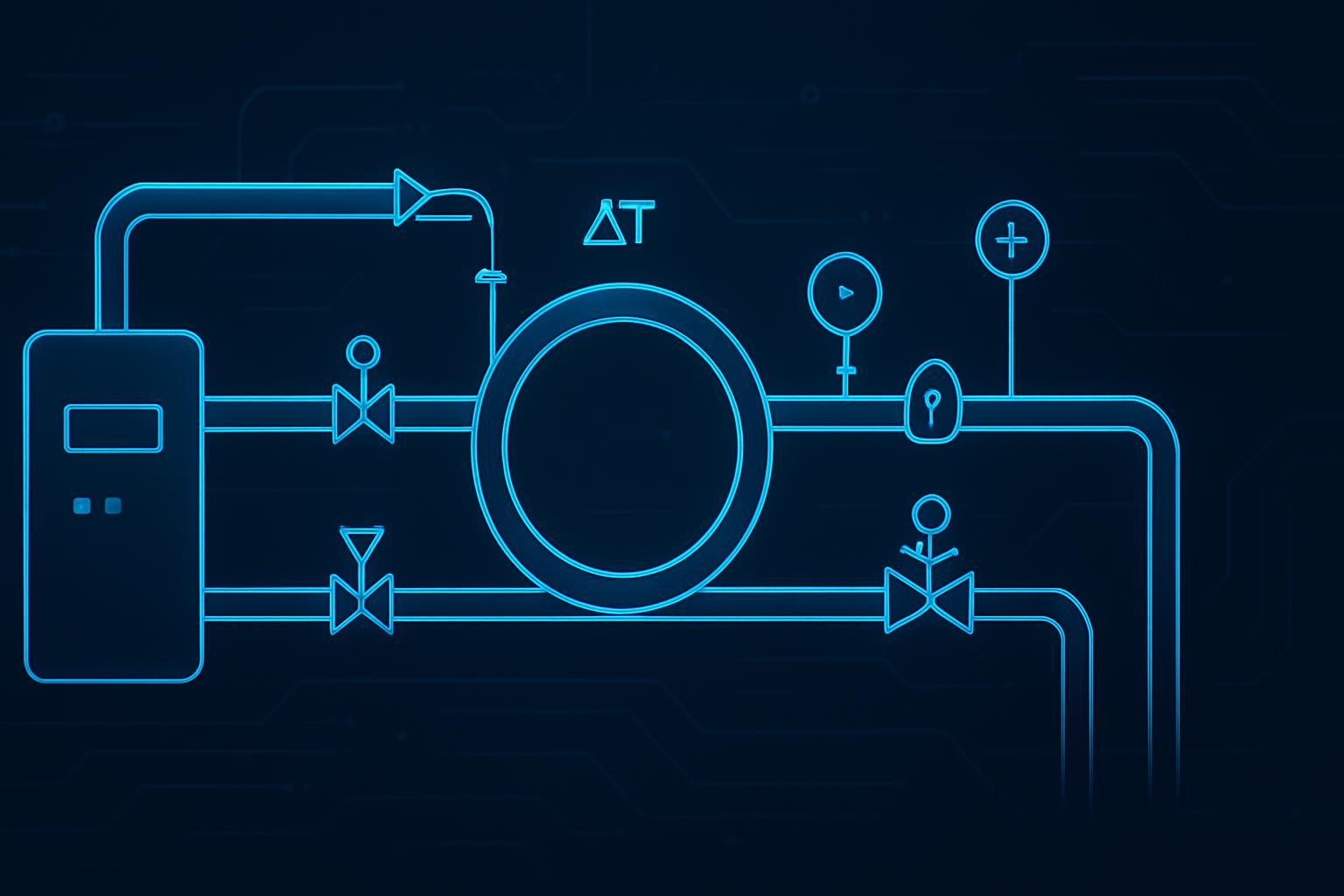
Direct-to-chip liquid cooling routes coolant through cold plates mounted directly on high-heat components (typically GPUs/CPUs). The loop is usually designed as a “two-loop handshake”:
A facility loop (chilled water, warm water, dry cooler loop, etc.)
A technology loop (the coolant delivered to the IT equipment), typically managed by a CDU
The design goal is controlled flow/temperature/pressure at the cold plate, with leak detection and isolation designed into the distribution system.
Key Takeaway: Direct-to-chip is “targeted liquid cooling.” It captures a large portion of the heat where it is generated, while the rest of the server may remain air-cooled.
Immersion cooling in plain terms
Immersion cooling submerges servers in an electrically non-conductive (dielectric) fluid. There are two main variants:
Single-phase immersion: the fluid stays liquid; it is pumped through a heat exchanger.
Two-phase immersion: the fluid boils at component surfaces and condenses on a condenser (more specialized, higher complexity).
Key Takeaway: Immersion is “whole-server liquid cooling.” It changes how you service hardware, handle fluids, and manage containment.
A note on “edge computing thermal management”
In an edge context, edge computing thermal management is less about chasing the lowest possible temperature and more about setting stable operating envelopes: consistent coolant temperatures, predictable alarms, and maintenance steps that can be executed safely by the people you actually have on site.
Quick comparison matrix (edge-focused)
Evaluation criterion | Direct-to-chip (cold plate) | Immersion cooling |
|---|---|---|
Best fit at the edge | Retrofit-friendly high density; incremental rollout | Greenfield or dedicated rooms where tank footprint and workflows fit |
Heat capture | High at CPUs/GPUs; often hybrid (some air remains) | Very high (entire server in fluid) |
Mechanical risk profile | More joints/hoses/quick disconnects; localized leaks | Fewer small joints but “big spill” containment becomes central |
SOP burden | Leak detection + isolation + commissioning “handshake” | Fluid management + service workflow + spill/containment planning |
Service model | Similar to traditional racks, with liquid safety layers | Hardware handling changes (drips, draining, drying, lift/ergonomics) |
PUE impact | Can reduce facility energy and IT fan energy | Often removes fan energy almost entirely; facility impact depends on heat rejection |
Procurement complexity | More components (CDU, manifolds, QDs, sensors), but familiar rack model | Fluid qualification + tank vendor + hardware compatibility + EHS acceptance |
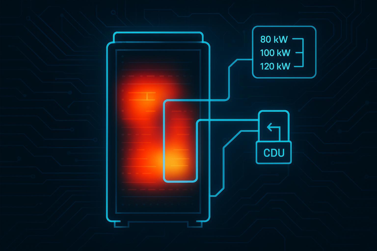
A useful density heuristic: one industry summary frames air cooling as workable up to ~20 kW/rack, rear-door heat exchangers up to ~100 kW/rack, direct-to-chip from ~100–175 kW/rack, and immersion above ~175 kW/rack (treat these as directional, not universal). See Network World’s 2026 rack-density overview.
Evaluation criterion 1: density headroom and “how much heat is actually captured”
At high density, “liquid cooling” can mean very different things operationally.
Direct-to-chip
Direct-to-chip typically targets the highest heat flux components first. That usually means strong thermals where it matters most (GPU/CPU junction-to-coolant path), but also a hybrid reality: other components (memory, NICs, VRMs, drives) may still rely on airflow.
For edge teams, the hybrid nature can be a feature. You can scale liquid where required without redesigning every operational workflow on day one.
A practical question to ask during design: what percentage of the rack heat is captured by liquid, and what remains for air? That answer drives everything from residual fan power to whether your room still needs cold-aisle management.
Immersion
Immersion often captures a larger share of heat because the entire server is in a fluid environment. It also reduces or eliminates server fans (depending on the design), which can materially change power distribution inside the rack.
The trade is commitment: you are adopting a different physical architecture (tanks) and a different service model.
If you are evaluating immersion cooling for AI GPUs, verify early whether your target server platforms are validated for immersion (materials compatibility, coatings, connectors, and support terms). That validation question is frequently the gating factor—not the thermal math.
Evaluation criterion 2: facility integration and retrofit reality
Edge sites frequently inherit constraints: available water loops (or lack of them), limited heat rejection options, limited redundancy, and limited floor loading assumptions.
Direct-to-chip: the “CDU + secondary loop” pattern
A direct-to-chip deployment typically centers around a CDU to manage flow, filtration, and the interface to facility water, plus manifolds/hoses that deliver coolant to racks. If you’re building an edge module or upgrading a small room, this can be attractive because it often supports rack-by-rack rollout.
Coolnetpower maintains several reference pages that are useful for orienting stakeholders who are new to the architecture:
Immersion: heat rejection can look simple, but workflows are not
Immersion cooling can reduce reliance on air handling, but it introduces integration requirements that often dominate edge feasibility:
Tank footprint and service clearance
Spill containment and drainage planning
Fluid storage, handling, filtration, and life-cycle plan
If you need a neutral taxonomy of liquid cooling approaches (including hybrid patterns that are common in practice), LBNL’s overview is a credible anchor: LBNL’s liquid cooling overview and taxonomy.
Heat rejection: don’t treat it as an afterthought
Both architectures still have to reject heat to the outside world. At the edge, you should treat heat rejection as a constraint that can dominate total system performance:
Dry coolers vs chillers: dry coolers can reduce complexity and water use, but can require larger outdoor footprint and careful part-load controls.
Supply temperatures: liquid cooling can often support higher supply temperatures than traditional air systems, potentially expanding economizer hours.
Redundancy model: edge sites may not be able to mirror hyperscale N+1 everywhere; clarify which failures you will tolerate and which require immediate shutdown.
This matters for PUE and for uptime. A “high-efficiency” liquid loop that depends on a single outdoor heat rejection path can still be operationally fragile.
Evaluation criterion 3: safety profile and SOP burden
The right question is not “Which is safer?” but:
What are the dominant hazards?
How do we detect early failure?
How do we isolate and recover without improvisation?
Third-party safety anchors you can cite
UL Solutions provides an accessible overview of safety certification considerations for liquid cooling in Safety certification of IT equipment cooling in data centers (UL Solutions, 2025), referencing hazard-based ICT equipment safety frameworks and certification programs.
For immersion fluids specifically, UL describes the certification framing in Immersion cooling fluid certification under UL 2417.
For broader engineering context on liquid cooling adoption (not a safety standard, but a reputable technical framing), ASHRAE provides a liquid cooling overview in “Emergence and Expansion of Liquid Cooling in Mainstream Data Centers” (ASHRAE, 2026).
Direct-to-chip: the leak is usually smaller, the number of leak points is higher
Direct-to-chip systems distribute coolant through more fittings and connections. That changes your safety engineering focus.
Most edge teams find it useful to think in three leak severities:
Seep: slow moisture at a fitting or cold plate interface
Drip: repeated droplets forming and falling into a tray/containment area
Spray: pressurized release with rapid propagation risk
The point of the classification is not terminology. It is to ensure your alarm model and response plan are proportional.
For direct-to-chip, common controls include:
contain and detect small leaks early,
design isolation so a single issue does not become a site-wide outage,
manage pressure energy with relief and controlled depressurization,
standardize de-energized maintenance (LOTO/work permits).
Immersion: containment and fluid handling become primary safety systems
Immersion’s safety story is often oversimplified as “dielectric fluid means no short circuits.” In practice, immersion shifts the dominant safety work to:
containment and drainage design (where does the fluid go?),
human factors (drips, slips, lifting, and exposure),
fluid management (filtration, storage, makeup fluid, and disposal).
Immersion can reduce some electrical shorting risk, but it does not eliminate electrical safety, operational errors, or contamination risks.
A practical “minimum controls” SOP set (edge-ready)
Below is a minimum set of controls you can require regardless of which architecture you choose. Think of this as what your commissioning plan must prove.
Control area | What you verify before go-live | Why it matters at the edge |
|---|---|---|
Alarm model | Leak, flow, ΔP, temperature, and pump alarms are mapped to clear actions | Edge incidents worsen when alarms are ambiguous |
Isolation design | You can isolate a branch/rack without draining the whole system | Keeps a small issue from becoming a full outage |
De-energize workflow | LOTO steps are written, trained, and rehearsed | Edge sites cannot “learn live” safely |
Containment | Drip trays / containment pan / drainage plan is physically verified | Controls slip hazard and equipment exposure |
Spares and tools | Hoses/QDs/sensors and the right tools are staged locally | Avoids multi-day downtime due to small parts |
Ownership | Facilities/IT/EHS responsibilities are explicit | Multi-stakeholder ambiguity causes delay |
Evaluation criterion 4: operations, maintenance, and staffing
If you have to operate with minimal on-site staff, operational simplicity matters as much as thermal capacity.
Direct-to-chip operations
Direct-to-chip can preserve familiar rack operations. Servers can often be serviced without the “wet hardware” workflow that immersion introduces. The main operational demand is discipline around inspections, fittings, and standardized procedures.
If you are evaluating multiple GPU liquid cooling systems, compare not only thermal performance, but also:
accessibility of isolation valves,
clarity of labeling and valve maps,
whether routine maintenance can be done without a full shutdown,
and whether spare parts are standard or bespoke.
Immersion operations
Immersion operations are feasible, but they are different. The service workflow (handling submerged hardware, managing dripping components, potentially staging drying/inspection) needs to be designed as carefully as the thermal system.
A good way to test immersion readiness is to walk through a real scenario:
A node fails at 2 a.m.
What is the safe removal procedure?
How do you prevent drips onto walkways and power distribution?
Where do you stage the component?
What is the inspection/dry-out process?
Who approves return-to-service?
If your team cannot answer those questions without improvisation, immersion may still be the long-term answer—but it is not yet the near-term deployment answer.
Staffing and skills: make them explicit
Both systems introduce new work. The mistake is assuming that new work will be absorbed “somehow.” Procurement-ready planning should include:
training requirements and refresher cadence,
who is authorized to disconnect/connect liquid lines,
escalation paths and vendor support SLAs,
and the minimum on-site inventory to recover from predictable failures.
Evaluation criterion 5: efficiency and PUE impacts
Start with the real definition of PUE
Power Usage Effectiveness (PUE) is defined as:
PUE = Total facility energy / IT equipment energy
The Green Grid’s white paper, WP49 “PUE: A Comprehensive Examination of the Metric”, is one of the most citable public references for how PUE should be measured and reported. PUE is standardized as a KPI in ISO/IEC 30134-2:2016.
How liquid cooling for edge AI GPUs affects PUE (and how to read it correctly)
Liquid cooling can reduce total site energy in two main ways.
First, it can reduce facility overhead (fans, air handling, and—depending on the architecture—chiller work). Second, it can reduce IT energy by lowering server fan power. That second effect is often missed in executive summaries.
Vertiv summarizes an analysis where introducing direct-to-chip liquid cooling reduced facility power by ~18.1% and total data center power by ~10.2%, yet PUE improved only modestly (about 1.38 → 1.34). Their explanation is straightforward: if IT power drops too, PUE may not move as much as total kWh. See Vertiv’s “Quantifying data center PUE when introducing liquid cooling” (2023).
Key Takeaway: Use PUE for consistent reporting, but compare architectures using total kWh and consistent boundaries. At the edge, also track operational efficiency indicators (alarms, interventions, and uptime) that PUE does not capture.
Common PUE misinterpretations to avoid
If you are comparing architectures (or reporting a pilot), the most common mistakes are:
comparing two PUE numbers with different measurement boundaries or different averaging periods,
ignoring the denominator effect (IT fan power changes),
using a “best observed PUE” moment instead of a consistent reporting interval.
In a procurement context, require that any PUE claims include boundary definition and a clear measurement method. If you cannot get that, treat PUE as directional only.
Evaluation criterion 6: cost drivers that actually matter at the edge
For awareness-stage readers, cost discussions are most useful when they map what changes rather than trying to produce a universal number.
Direct-to-chip: cost drivers
Direct-to-chip cost is often driven by the distribution layer: CDUs, manifolds, hoses, quick disconnects, sensors, and the commissioning effort required to validate the handshake. In procurement terms, you are paying for a repeatable “rack plumbing + control” system.
Immersion: cost drivers
Immersion cost is often driven by tanks, fluids, and workflow design: fluid procurement and life-cycle, filtration, containment/drainage, and service procedures. In procurement terms, you are paying for a “new physical format” that changes IT operations.
The “hidden cost” category: risk management work
A practical way to compare architectures is to estimate the total operational effort required for:
writing and maintaining SOPs,
training and re-training,
auditing compliance,
and handling exceptions.
At the edge, this work can be more expensive than in a large campus because it cannot be spread across specialized teams. Include it in your decision criteria even if you do not assign a perfect number.
Who should choose which (edge scenarios)
Consider direct-to-chip first if…
Direct-to-chip is often the pragmatic first step for high-density edge AI cooling when you need incremental rollout and you want to preserve a rack-based service model.
Consider immersion if…
Immersion can be appropriate when you can design space, containment, and workflows up front—and when the site can consistently execute the fluid-management discipline required.
Many edge teams will land on a hybrid pathway
It is common to start with direct-to-chip (plus optimized air for residual heat) and then evaluate deeper liquid architectures as density and operational maturity increase. CoreSite’s overview reinforces the prevalence of hybrid approaches in practice: “Liquid cooling steps up for high-density racks and AI workloads” (CoreSite).
Procurement-ready checklist: questions that prevent late surprises
If you want this comparison to translate into a clean RFP conversation, the questions below are the ones that typically prevent late-stage redesigns.
Question to answer early | Why it changes the architecture |
|---|---|
What heat rejection method do we have at this edge site? | Determines chiller dependence and redundancy model |
What is the maximum acceptable spill volume and where is it contained? | Often the deciding constraint for immersion |
Who owns SOPs and training (Facilities vs IT vs EHS)? | Avoids “everyone assumed someone else” |
What is the planned density now vs in 18–24 months? | Prevents short-lived solutions and stranded CAPEX |
What is the service workflow for a failed node at 2 a.m.? | Tests whether immersion workflow is realistic |
Next steps (low-friction)
If you want a procurement-friendly next step, request a commissioning/SOP checklist you can attach to an RFP for GPU liquid cooling systems in edge sites.
Start with Coolnetpower’s overview hub: high-density liquid cooling solutions
Optional read: Coolnetpower case study (for context)
Coolnetpower published a case-study-style overview here: High-density compute clusters: advanced liquid cooling for AI & HPC. Treat it as an optional reference; for design decisions, rely on your own measured requirements and third-party standards.
FAQ
Is immersion always more efficient than direct-to-chip?
Not always. Immersion can reduce fan power and shift more heat into a liquid loop, but overall efficiency depends on how heat is rejected (dry coolers vs chillers), part-load behavior, and controls. Also, PUE may not reflect total kWh savings cleanly when IT fan power changes.
Does liquid cooling automatically guarantee a “good PUE”?
No. PUE is a facility/IT ratio, and it depends on site boundaries and how you measure. Use The Green Grid guidance for reporting, and compare architectures with total kWh and consistent boundaries.
Are “liquid cooled edge servers” a special hardware class?
Usually, “liquid cooled edge servers” just means standard server platforms configured for cold plates or for immersion compatibility. The important question is not the label—it is whether the server, coolant, connectors, and operating envelopes are all validated together and supported by a clear maintenance workflow.
What safety standard should we start with?
Start by aligning with hazard-based ICT equipment safety requirements (often referenced via IEC 62368-1) and use safety certification guidance from bodies such as UL Solutions to structure your compliance and testing approach.