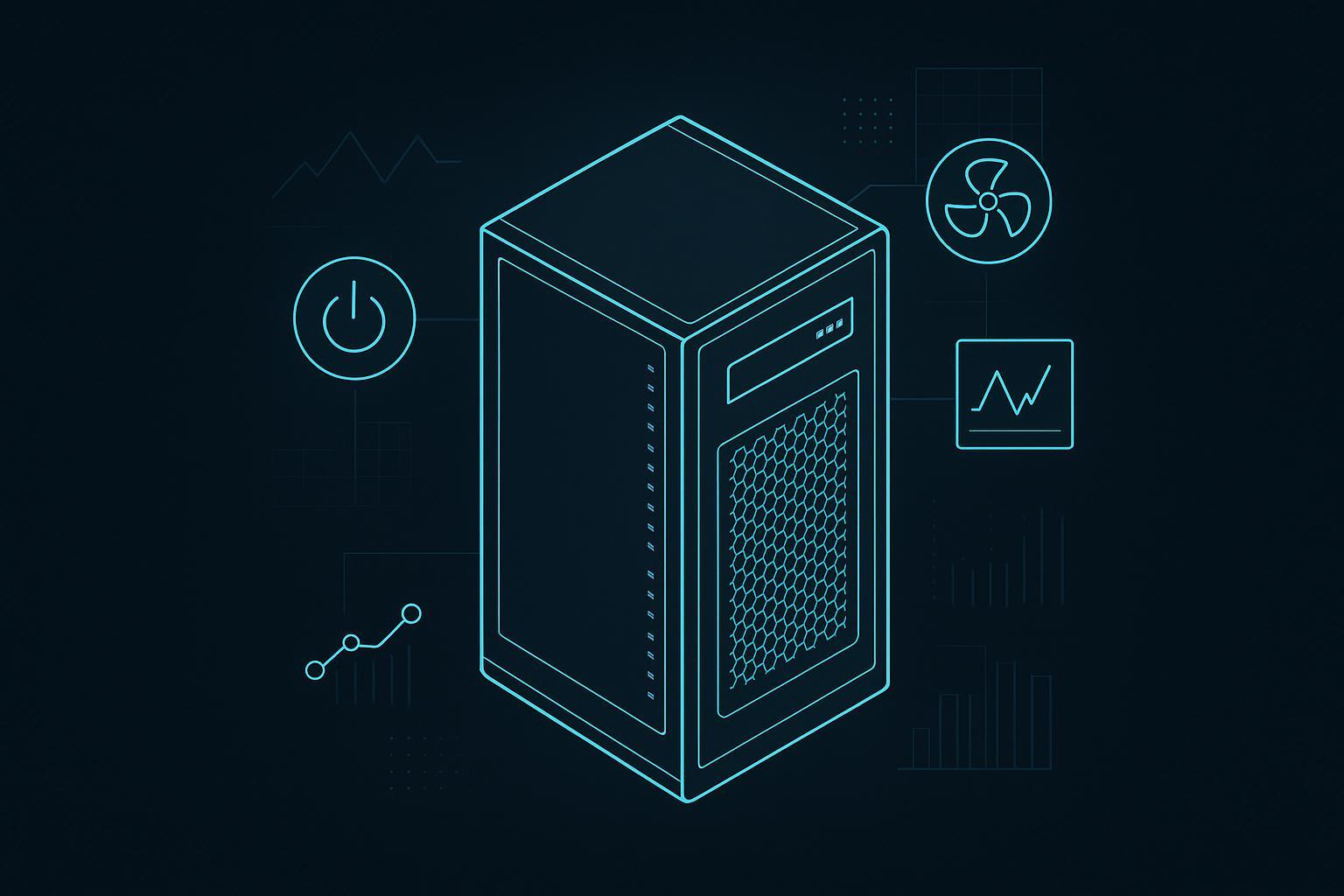
Edge AI racks live in an awkward middle ground: too dense for “classic” server-room assumptions, but often too constrained (space, electrical service, staffing, water) for a full liquid-native build. At 20–40 kW per rack, your outcome depends less on picking a single cooling technology and more on getting the interfaces right: airflow separation, power distribution, redundancy boundaries, and controls.
This 20–40 kW rack cooling best practices guide compares air, hybrid, and liquid approaches, shows common redundancy options, and gives sizing tables you can adapt for early design and RFPs.
Table of Contents
ToggleKey takeaways
20–30 kW/rack is often achievable with optimized air if containment and airflow control are treated as first-class design requirements.
20–40 kW/rack is a natural “hybrid zone” where rear-door heat exchangers (RDHx) or close-coupled approaches can offload a meaningful share of heat without committing to full liquid everywhere.
Plan redundancy as a boundary problem (what’s redundant: UPS modules? distribution paths? pumps? valves? whips?)—because a single non-redundant downstream element can negate upstream redundancy.
Use PUE carefully: it’s useful for comparing designs under the same measurement boundary and load factor, but misleading when used as a single target across different edge sites.
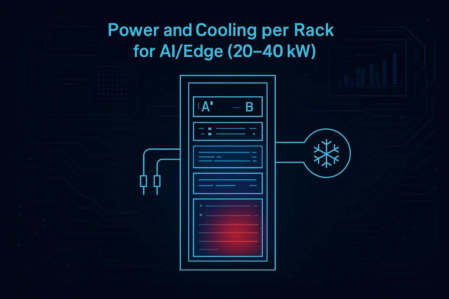
Define the envelope first: power and cooling per rack for AI edge (20–40 kW)
This section sets the baseline for power and cooling per rack for AI edge deployments in the 20–40 kW band—what it implies physically, and what tends to break first if you don’t design the interfaces.
At a high level, almost all rack electrical power becomes heat inside the space. So a 30 kW rack implies you must remove roughly 30 kW of heat continuously (plus losses from power conversion and fan energy).
Two practical implications for edge sites:
Air becomes a volume problem. The higher the rack heat load, the more airflow you need—and the more sensitive you become to bypass, recirculation, and fan power.
Power becomes a distribution problem. The question is not only “Do I have enough utility power?” but “Can I deliver it to each rack with the right voltage, breaker sizing, phase balance, and A/B architecture?”
Key Takeaway: At 20–40 kW/rack, the “best” solution is usually the one that keeps airflow and power distribution predictable under failure conditions.
Best practice 1: Treat air management as a design system, not an ops tweak
Why it matters
Air cooling can fail “quietly” first: a site looks fine at average load but trips GPU throttling, inlet alarms, or localized hotspots during bursts. The root cause is typically airflow mixing, not insufficient nameplate cooling.
How to implement
Design for strict separation: hot aisle/cold aisle with containment (or a close-coupled alternative) and disciplined blanking/sealing.
Instrument early: rack inlet temperature sensors and differential pressure across containment zones.
Make serviceability explicit: can doors open, filters be replaced, and cable cutouts remain sealed after changes?
Failure mode if you skip it
You “buy” extra cooling capacity to compensate, then lose it to bypass air. Fan energy increases, PUE worsens, and the site becomes unstable at peak workloads.
Best practice 2: Use a simple cooling selection rule for 20–40 kW
Why it matters
There’s a temptation to debate air vs liquid as a binary choice. In edge AI, the pragmatic question is often: what fraction of the rack heat can we remove close to the source without rebuilding the entire facility?
How to implement
Use this rule-of-thumb framing (validate with your OEMs and site constraints):
Optimized air (often best fit around ~20–30 kW/rack)
Requires strong containment discipline and enough “air-moving budget” (fan power, floor/ceiling paths, in-row options).
Hybrid / close-coupled (often best fit around ~20–40 kW/rack)
Rear-door heat exchangers, in-row units, or other close-coupled strategies to reduce room-level heat burden.
Rear-door heat exchanger vs direct-to-chip liquid cooling (common decision point in this band)
RDHx is often used as a transition step when you want to reduce room load without changing servers, while direct-to-chip is used when GPU heat flux and sustained density make airflow management impractical.
Direct-to-chip liquid (commonly justified as densities push beyond ~20 kW toward ~50 kW and above)
When airflow becomes impractical or when the workload is GPU-dense and sustained.
Direct-to-chip becomes increasingly relevant as racks rise toward ~20 kW and approach ~50 kW, where cold plates, a CDU, leak detection, and fluid-management procedures become central to safe operation.
Failure mode if you skip it
You either overbuild the room (big CAPEX and fan energy) or underbuild the rack interface (local hotspots and instability).
Best practice 3: If you’re in the hybrid zone, design RDHx as an engineered interface (not a bolt-on)
Why it matters
Rear-door heat exchangers (RDHx) can be an effective bridge between air-only and full liquid. But they only work as well as their integration: clearance, weight, water loop quality, and control.
How to implement
Use RDHx capacity ranges as a planning anchor, then validate with your rack/server vendors:
HPE’s published RDHx capacity ranges provide a practical reference point: 14–35 kW (M12) and 35–55 kW (M14), per HPE Rear Door Heat Exchanger QuickSpecs.
Operationally, treat RDHx as a small system:
Define water loop ownership and commissioning responsibility.
Confirm door swing/clearance and rack structural implications.
Decide control philosophy: fixed flow vs modulating valves, alarms, and what happens on sensor failure.
Failure mode if you skip it
You hit a “paper capacity” that isn’t stable in practice: maintenance becomes difficult, alarms are noisy, and you end up reverting to room cooling when the RDHx should be carrying the load.
Best practice 4: N+1 vs 2N redundancy for rack power and cooling (and what it actually covers)
Why it matters
Many edge projects accidentally mix a high-level redundancy target with non-redundant downstream elements (feeds, whips, valves, a single pump, or a single CDU). The result is a system that looks redundant on a one-line diagram but still fails like an N design.
How to implement
Use clear definitions, then explicitly list which components are in-scope.
CoreSite’s redundancy explainer is a clean reference for definitions:
N: minimum capacity needed for full load
N+1: N plus one extra component
2N: fully mirrored, independent systems
2N+1: 2N plus one extra component
(See: a standard “N / N+1 / 2N” redundancy definition reference.)
Then decide where you apply redundancy:
Subsystem | Common edge pattern | Why it’s common | Hidden pitfall |
|---|---|---|---|
Utility + generator | N+1 | single failure tolerance | fuel logistics and testing scope |
UPS | N+1 modular | scalability + maintainability | upstream redundancy can be negated by downstream single-path distribution |
Rack feeds | 2-path A/B | enables maintenance + reduces single points | A/B is only meaningful if both feeds are truly independent end-to-end |
Cooling | N+1 | cost-effective vs 2N | a single non-redundant pump/valve can dominate failure risk |
Failure mode if you skip it
You pay for redundancy without getting concurrently maintainable operation. Maintenance windows become risky, and incident response becomes improvisational.
Best practice 5: Size rack power delivery with real “usable kW per feed,” not nameplate optimism
Why it matters
High-density racks often fail on distribution before they fail on total facility power. You can have sufficient UPS capacity but insufficient feeder/branch architecture to deliver power safely.
How to implement
For early-stage sizing, anchor on a conservative continuous-load assumption.
Server Technology provides a commonly cited example for usable power on a 208V, 60A, three-phase feed:
Usable kW ≈ 208 × 60 × √3 × 0.8 = 17.3 kW per feed (a common worked example for a 208V, 60A, three-phase feed using an 80% continuous-load assumption).
That immediately suggests why many 20–40 kW racks end up with:
Two independent 3-phase feeds (A/B) for both capacity and resilience
Or a move to higher-voltage distribution (where appropriate) to reduce conductor/cable complexity
Failure mode if you skip it
You end up adding “emergency” whips and panels late in the project, increasing risk, downtime exposure, and commissioning time.
Air vs liquid cooling for high-density racks: air vs hybrid vs liquid (20–40 kW)
Use this as a planning comparison (not a vendor selection):
Attribute | Optimized air | Hybrid (e.g., RDHx / close-coupled) | Direct-to-chip liquid |
|---|---|---|---|
Best fit (20–40 kW context) | Lower end of band, bursty loads | Middle of band; transitional sites | Upper end of band; sustained GPU density |
Primary constraint | airflow, mixing, fan power | integration + water loop + controls | fluid management + service model + leak detection |
Retrofit friendliness | moderate | often good if water loop is feasible | varies; depends on server support and facility loop |
O&M skill requirement | moderate | moderate-high | higher (procedures, sampling, spares) |
“Gotcha” failure | recirculation → hotspots | poor integration → alarms/underperformance | poor leak detection/procedures → downtime risk |
To keep the body vendor-neutral, treat published capacity figures as planning anchors (not guarantees). For example, HPE publishes RDHx ranges of 14–35 kW and 35–55 kW for specific models in its Rear Door Heat Exchanger QuickSpecs.
Redundancy matrix: what changes in sizing?
Use this matrix to align design intent with what you actually size:
Redundancy target | What it usually means | What to size/verify | Practical note |
|---|---|---|---|
N | just enough capacity | single power path; single cooling path | simplest, but maintenance = downtime |
N+1 | one spare module/unit | modular UPS, extra cooling unit, spare pump capacity | ensure failover logic is tested and documented |
2N | mirrored independent paths | true A/B feeds, independent distribution, segregated failure domains | costs more; often reserved for the most critical edge sites |
Best practice 6: Use a sizing table to keep power and cooling decisions coupled
Sizing table: 20–40 kW per rack (starter planning numbers)
These are starter sizing anchors for early planning; validate with your electrical engineer and OEMs.
Target rack load | Power delivery (starter) | Cooling approach (starter) | Key checks |
|---|---|---|---|
20 kW | 2× feeds with headroom; phase-balance plan | optimized air or hybrid | containment discipline; inlet sensor plan |
30 kW | 2× 3φ feeds often required | hybrid strongly favored | RDHx integration (clearance, loop); maintenance plan |
40 kW | 2× feeds minimum; consider higher-voltage strategy | hybrid or direct-to-chip | leak detection + fluid procedures; commissioning scope |
When quantifying feed capacity, a common reference point is the ~17.3 kW usable per 208V/60A/3φ feed example shown by Server Technology. It makes the A/B feed approach intuitive: two feeds provide both redundancy and capacity.
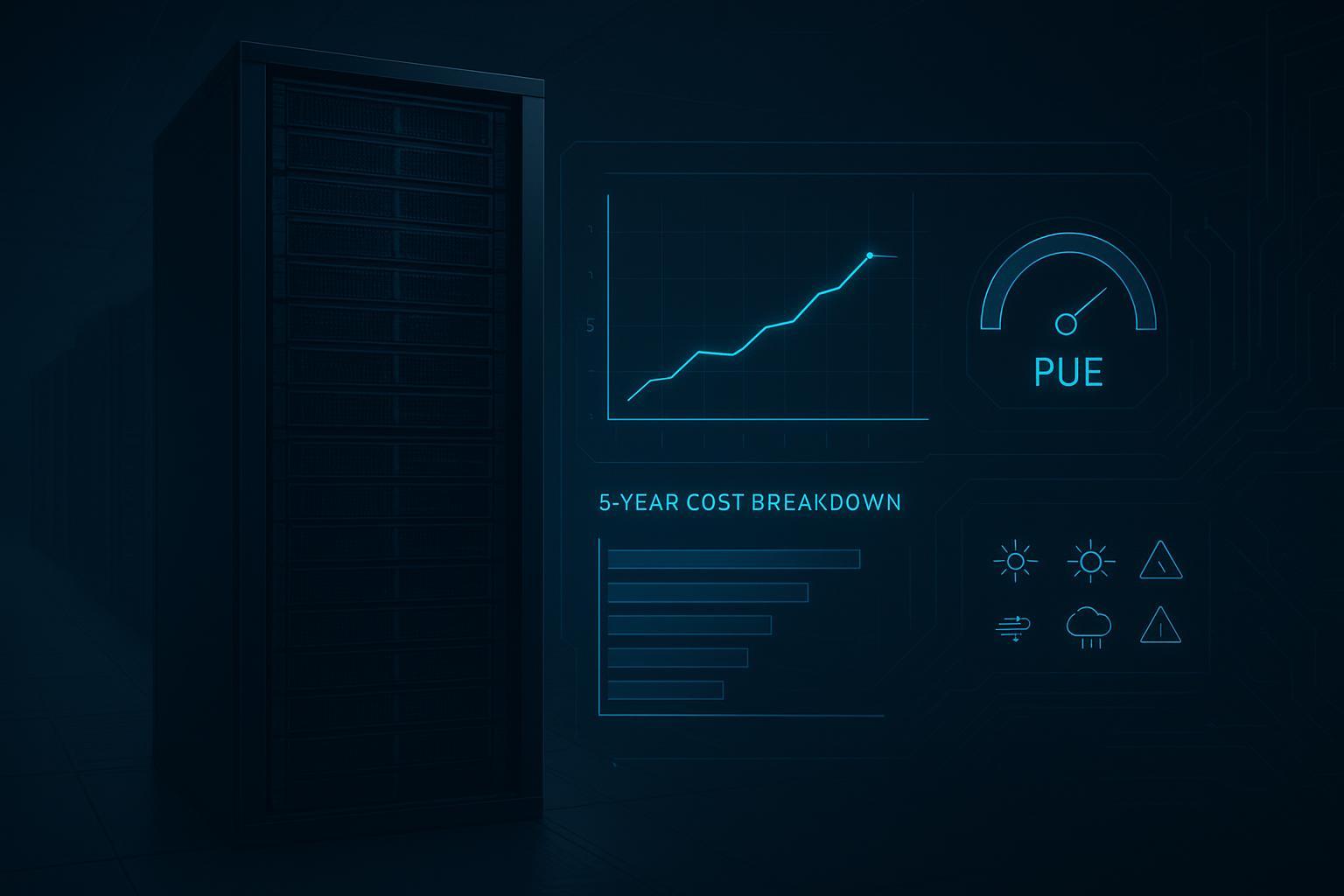
Best practice 6: PUE targets — use ranges, and document your measurement boundary
PUE is defined as total facility power divided by IT power; it’s useful, but only comparable if you measure it consistently. Vertiv’s explainer provides a clear definition and interpretation context in its “What is PUE and what does it measure?” article.
For context on what “best possible” can look like at scale, hyperscale operators have reported fleet-wide trailing PUE performance publicly—but edge sites typically face different utilization and boundary realities.
Pro Tip: Write your PUE requirement as “PUE under defined boundary and load factor,” not as a single number. Otherwise you’ll optimize measurement, not performance.
Early-stage checklist (copy/paste into an RFP or design review)
Power
What is the rack’s target steady-state kW and peak kW profile?
What is the per-rack distribution approach (A/B feeds, busway vs whips, receptacle standard)?
What continuous-load assumptions are being used for breaker sizing and headroom?
What’s the commissioning test plan for failover (UPS module loss, feed loss, breaker trip)?
Cooling
Is the design optimized air, hybrid (RDHx/close-coupled), or direct-to-chip—and why?
What is the airflow separation/containment strategy and how will bypass be controlled over time?
If hybrid/liquid: who owns water quality, filtration, sampling, and leak response?
What alarms are “actionable” vs “informational,” and how do you prevent alarm fatigue?
Reliability and operations
Which redundancy model is targeted for each subsystem (power chain, distribution, cooling loop, controls)?
What are the true single points of failure downstream of the UPS or cooling plant?
What is the maintenance window plan (and what can be serviced without downtime)?
FAQ
What’s feasible with air cooling vs liquid cooling at 20–40 kW per rack?
At the lower end of the band, optimized air can work if airflow separation is engineered and maintained. As you move toward 40 kW sustained, close-coupled and liquid approaches become more compelling because they reduce reliance on moving massive air volumes and help control hotspots.
What redundancy levels are standard for AI/edge racks?
It varies by risk tolerance, but N+1 is common for modular capacity planning, and 2-path A/B distribution is common where concurrent maintenance matters. A good starting point is a clean set of definitions for N, N+1, and 2N (for example, CoreSite’s “N+1 vs 2N” overview linked earlier in this guide), then document what each label covers in your design.
How do you size PDUs and busways for 20–40 kW racks?
Start with a “usable kW per feed” calculation under continuous-load assumptions, then decide whether you need two independent feeds per rack for both capacity and resilience. The worked example in Server Technology’s distribution explainer (linked earlier in this guide) shows why a single 208V/60A/3φ feed is often not enough for 20–40 kW designs.
What PUE can edge and modular sites realistically achieve?
Use ranges, not a single promise—and define the measurement boundary. PUE is best used to compare design options under consistent conditions (load factor, boundary, climate), as described in Vertiv’s PUE explainer linked earlier in this guide.
Next steps
If you want, I can turn the checklist and tables above into a one-page “AI/edge 20–40 kW rack RFP addendum” you can hand to EPCs and module vendors.
Appendix: Coolnetpower liquid-ready options (examples only)
Below are vendor examples you can reference when you want liquid-ready options—these are not required to apply the sizing framework above.
Liquid cooling solutions: Coolnetpower Liquid Cooling
CDU component example: Coolnetpower CDU
Micro data center cabinet example: MetaRack
Modular row solution example: MetaRow
Related reading: