Introduction
AI and HPC are reshaping thermal design. The core shift isn’t just “more heat”—it’s higher rack densities, faster deployment cycles, and mixed halls where legacy IT and GPU clusters must coexist under one operational model.
This article is a forward-looking decision guide for CTOs, data center directors, and thermal engineers who need to choose cooling approaches that scale without increasing operational risk, including where liquid cooling for AI racks should start and how to phase it into mixed-density halls.
We cover air, hybrid approaches, direct-to-chip (D2C) liquid, immersion, and free cooling/economization.
The practical intent is simple: use the strategy matrix to map density, climate/water constraints, and retrofit limits to a cooling path you can pilot, validate, and scale.
Density realities
Air limits at 20–40 kW/rack
Air cooling can remain viable in the 20–40 kW/rack band, but only when airflow is treated as a system—not a default. The limiting factor is usually not one component; it’s the combination of:
Containment effectiveness (leakage, bypass air, recirculation)
Fan power and acoustic limits at higher airflow rates
Coil approach temperatures and chilled-water plant constraints
The ability to keep IT in a reliability-focused temperature/humidity envelope—not just “survival mode”
A standards-aligned way to think about this is to separate normal operation from excursions. ASHRAE TC 9.9 frames data center environmental control using “recommended” versus “allowable” envelopes (with different risk and reliability implications), and that distinction matters when you’re deciding whether to extend air cooling or introduce liquid for the next density tier (see ASHRAE TC 9.9 thermal environmental classes and envelopes).
Key Takeaway: If you’re stretching air to sustain 20–40 kW/rack, treat containment + controls as mandatory infrastructure. “It can run” is a weaker criterion than “it can run predictably within a recommended envelope.”
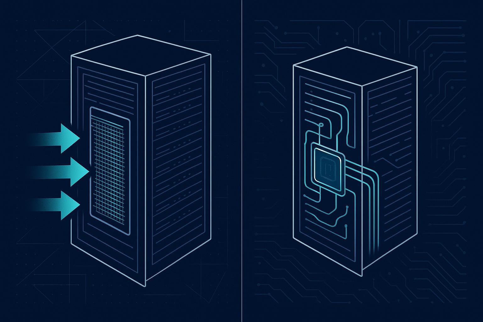
Liquid pathways ≥40–60 kW
Once you plan for sustained density at (and above) ~40–60 kW/rack, liquid becomes less a “premium option” and more a risk-control tool: it allows you to remove heat with lower transport energy, reduce hot-spot volatility, and zone high-density loads without redesigning the entire hall.
In practice, the liquid pathway is not one thing. It’s a choice between architectures that move the facility/IT boundary:
RDHx (rear door heat exchangers) as a bridge for mixed halls (often attractive for brownfield rows)
D2C liquid where CPU/GPU heat dominates and you want repeatable rack-level performance
Immersion cooling where density is extreme and you can commit to a dedicated operating model
For a neutral primer on why liquid cooling changes the heat-transport equation, LBNL’s overview is a useful baseline (see LBNL’s liquid cooling overview).
Climate and water constraints
Climate sets the ceiling on “free cooling hours,” and water policy sets the constraints on how you achieve them.
In temperate/cold climates, economizers can materially reduce mechanical cooling runtime—if controls and filtration are maintained.
In hot-humid climates, humidity control and corrosion risk tend to reduce air-side economizer practicality.
In hot-dry regions, it’s often water risk (scarcity, cost, permitting, public scrutiny) that becomes the binding constraint.
Two pragmatic references to ground planning assumptions:
The U.S. DOE’s guidance on climate suitability and best practices (see the DOE best-practice guide for energy-efficient data center design).
LBNL’s economizer research highlighting energy benefits alongside indoor particulate considerations (see LBNL research on economizer use and indoor particle impacts).
⚠️ Warning: Free cooling designs live or die on operations. If filtration maintenance, sensor calibration, and control tuning aren’t resourced, the “theoretical hours” don’t translate into stable performance.
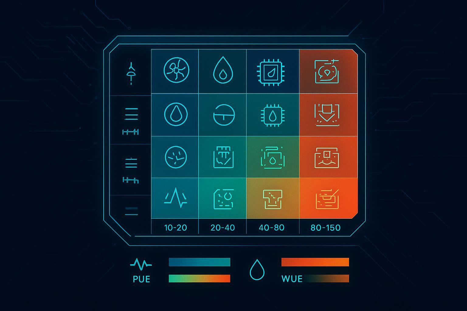
Strategy matrix: data center cooling strategies
Decision inputs and tiers
Use a small set of inputs to keep decisions comparable across sites and stakeholders. For most enterprise programs, the following inputs are enough to classify a hall into tiers and select a first-path solution:
Core inputs
Density tier: peak and sustained kW/rack (plus how uneven it is across the room)
Workload mix: AI/HPC vs general compute; expected roadmap over 12–36 months
Retrofit constraints: downtime tolerance, space for CDUs/heat exchangers, routing paths, floor loading
Facility interfaces: available chilled water/facility water temps, dry cooler capability, redundancy model
Water constraints: WUE targets, water risk policy, local permitting constraints
Controls maturity: BMS/DCIM telemetry coverage, change management discipline, alarming and response readiness
A simple tiering approach that keeps planning honest:
Tier 1 (≤20 kW/rack): optimize air first (containment, airflow hygiene, controls)
Tier 2 (20–40 kW/rack): air plus targeted augmentation; consider RDHx for hotspots or constrained aisles
Tier 3 (40–80 kW/rack): hybrid becomes default; D2C for AI rows, with air/RDHx for residual heat
Tier 4 (80–150 kW/rack): liquid-dominant AI/HPC blocks; design facility loops and redundancy around it
Tier 5 (150+ kW/rack): immersion or specialized liquid architectures; treat as a distinct operating domain
data center cooling strategies
The goal of data center cooling strategies in the AI era isn’t choosing one technology globally—it’s choosing a portfolio that matches density variation and retrofit reality.
Use this compact mapping as a starting point:
Scenario | Default strategy | Why it works | Watch-outs |
|---|---|---|---|
Mixed enterprise hall, 10–30 kW/rack | Optimized air + containment | Lowest complexity; preserves standard ops | Needs airflow hygiene discipline; avoids localized “quick fixes” |
Brownfield row creeping past 30–40 kW/rack | RDHx as bridge | Minimal IT change; localizes retrofit impact | Condensation control, water-side integration, maintenance access |
New AI pod, 40–80 kW/rack | D2C-first hybrid | Removes heat at source; repeatable per-rack performance | Leak detection, coolant quality, commissioning, skills |
Dedicated AI/HPC block, 80–150 kW/rack | Liquid-dominant (warm-water capable) | Enables higher return temps; improves heat reuse options | Controls integration and redundancy become first-order design |
Extreme density, uniform fleet | Immersion | High heat transfer; simplifies air side | Operational model is different (service, fluid handling, safety) |
Standards-aligned envelopes
When you standardize an envelope, you reduce risk during expansion and audits.
Thermal envelope (air-side zones): Use ASHRAE TC 9.9 to separate “recommended” (target for normal operations) from “allowable” (tolerable excursions). Treat “allowable” as an exception-management zone, not the design center.
Energy and water metrics: Use The Green Grid definitions for consistent reporting. For measurement discipline, the reference point for PUE is The Green Grid’s PUE measurement guidance. For water, align to a standard definition such as The Green Grid’s Water Usage Effectiveness (WUE) v1. If you’re pursuing heat reuse, use ERE/ERF consistently (see The Green Grid’s Energy Reuse Effectiveness (ERE) paper).
A practical way to apply this in design reviews: insist that every proposed cooling path provides (1) a normal operating envelope, (2) an excursion envelope, and (3) an instrumentation plan that proves you’re operating where you think you are.
Deployment pathways
Brownfield hybrid upgrades
Brownfield success is usually about minimizing blast radius.
A phased pathway that reduces operational surprises:
Fix airflow fundamentals first: containment integrity, blanking, cable management, tile/grille discipline.
Pilot a single high-density row: choose the row with the clearest business case (persistent hotspots, high-value AI loads).
Add localized augmentation: RDHx is often the least disruptive way to reduce room heat rejection for a specific row.
Introduce a liquid boundary deliberately: when moving to D2C, define a clear facility-to-IT interface (isolation, redundancy, leak detection, commissioning).
The key decision is whether your brownfield constraints are mostly “air-side” (fixable with containment and local heat exchange) or “architecture-side” (requiring a rack/row liquid loop with a defined boundary).
Greenfield AI/HPC blocks
Greenfield programs can make one critical move that brownfields can’t: design AI/HPC as a distinct block with a repeatable template.
A good block design is modular in three dimensions:
Thermal: liquid loop sized for AI loads with room for residual air cooling
Mechanical: expansion-ready distribution (manifolds, valving, isolation)
Operational: commissioning and alarm response designed before the first rack arrives
If heat reuse is on the roadmap (campus heating, district energy), warm-water-capable liquid designs can improve the grade of recoverable heat and make ERE reporting meaningful.
Controls and integration
Controls are where hybrid either becomes scalable—or becomes a one-off science project.
A controls-and-integration checklist to keep hybrid liquid-ready without overcomplicating it:
Define the boundary: what’s facility water vs secondary coolant loop; what sensors prove separation (T, flow, ΔP, conductivity where relevant)
Instrument for the failure modes: leak detection zoning, drip trays where appropriate, valve state feedback, pump health
Integrate telemetry: publish key points to DCIM/BMS so alarms are actionable (not just “something is wrong”)
Operationalize change control: setpoint governance, maintenance windows, and clear rollback procedures
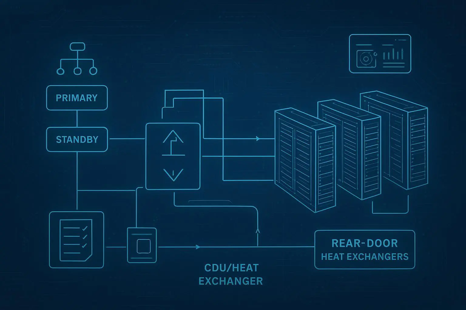
When describing hybrid “liquid-readiness,” it helps to use real reference-architecture components as examples rather than abstractions. For instance, many hybrid designs use a CDU as a thermal/hydraulic boundary between facility water and the rack/row loop. Coolnetpower’s taxonomy of common building blocks (cold plate liquid cooling, immersion, CDUs) can be referenced educationally without assuming a single-vendor outcome (see Coolnetpower’s liquid cooling portfolio).
Economics and sustainability
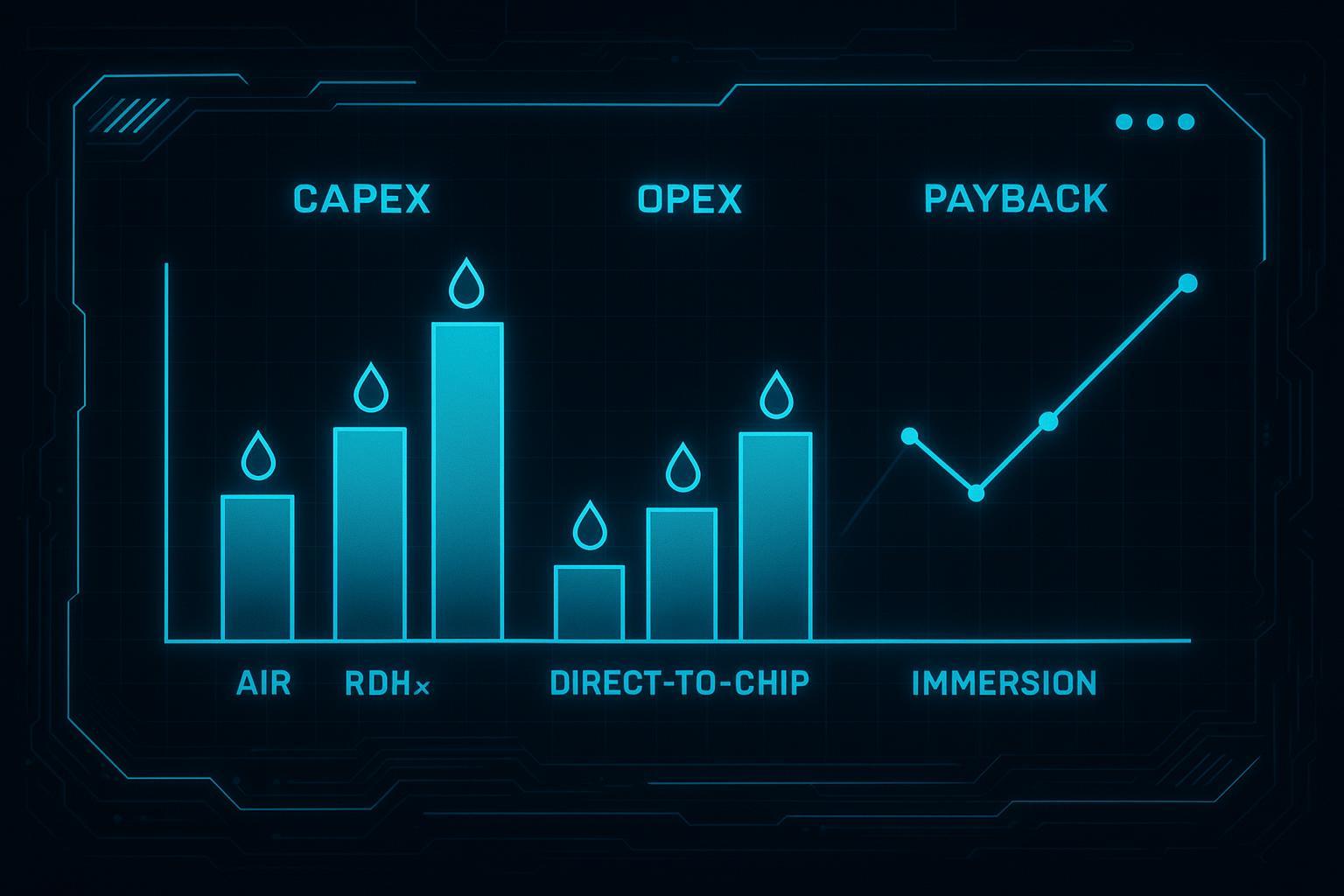
CAPEX/OPEX and payback
For AI-era cooling, economics tends to be driven less by “which option is cheapest” and more by which option reduces the cost of the next unit of capacity.
A clean way to compare options is to separate cost drivers:
CAPEX drivers: containment and air distribution upgrades (air); door exchangers and water-side tie-in (RDHx); CDUs, manifolds, cold plates, and commissioning (D2C); tanks, fluids, handling equipment, and specialized service workflows (immersion).
OPEX drivers: fan power and compressor runtime (air-heavy); pump power and control tuning (liquid-heavy); maintenance labor and spare strategy across both.
Payback is usually unlocked by one (or more) of these levers:
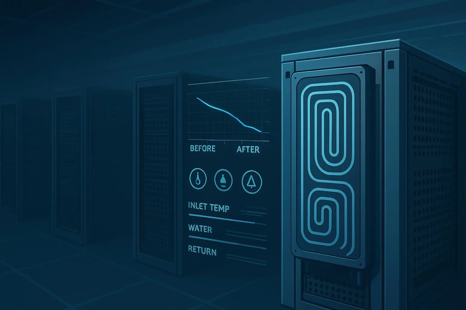
Reduced mechanical cooling runtime (more economization hours, higher supply temps)
Reduced fan power (less airflow needed per kW)
Higher usable density in the same footprint (deferring new build-out)
Improved thermal stability for GPU clusters (reducing throttling risk)
To keep ROI discussions credible, model scenarios (conservative/base/aggressive) and document assumptions (IT load profile, energy/water tariffs, downtime cost). Avoid single-number promises.
PUE/WUE/ERE trade-offs
PUE, WUE, and ERE answer different questions—and optimizing one can hurt another.
PUE reflects infrastructure overhead relative to IT load.
WUE forces the water conversation into the engineering review instead of after the fact.
ERE credits beneficial external heat reuse and should be reported only when there is credible off-take and metering boundaries.
A practical governance rule: require teams to report PUE and WUE for every option, and only include ERE where heat reuse is real and measurable.
Heat reuse and WUE policy
Heat reuse and WUE policy are increasingly intertwined.
If water is constrained, designs that reduce evaporative dependence (or shift to closed-loop approaches where practical) can be favored—even if it slightly increases energy overhead.
If heat reuse is feasible, higher coolant return temperatures can improve the usability of recovered heat and reduce additional lifting energy.
Use the decision matrix to surface these policy choices early, not as a late-stage sustainability add-on.
Operations and risk
Leak detection and redundancy
Liquid doesn’t have to be high risk—but it does require explicit risk engineering.
Operational best practices commonly include:
Layered leak detection (point + rope sensors) with clear zoning and response playbooks
Isolation valves that can segment the loop without taking down an entire pod
Redundancy where it matters (pumps, controls power feeds), plus maintenance bypasses
Commissioning that validates flow balance, ΔP margins, and alarm logic—not only cooling capacity
If your architecture uses a CDU boundary, ensure the organization treats the CDU as a monitored system (not a hidden box). As one example of typical CDU features and interfaces (manifolds, quick connectors, facility water tie-in), see Coolnetpower’s product page for Coolant Distribution Units (CDU).
Mixed-density airflow hygiene
Hybrid halls fail in predictable ways when airflow “hygiene” is ignored.
Common failure modes to actively prevent:
Empty U-spaces and cable clutter creating recirculation paths
High-density rows pulling air from unintended pathways due to pressure imbalances
Inconsistent blanking/containment discipline across teams
Temporary changes (maintenance, lab equipment) that become permanent without review
Treat airflow hygiene as an operational standard with audits and ownership, especially when only part of the hall is liquid-cooled.
Skills and maintenance
A hybrid facility needs two kinds of readiness:
Technical readiness: staff can service both air-side and liquid-side equipment safely (connectors, coolant handling, water quality basics).
Process readiness: alarms have owners; maintenance windows and rollback procedures exist; commissioning is repeatable.
The skills gap is real, but it’s manageable if you plan training and spares strategy as part of the deployment pathway—not after the first incident.
Conclusion
Hybrid wins in the near term because most sites will remain mixed-density for years. Liquid leads in dedicated AI/HPC blocks because it provides a scalable path for sustained high density with better controllability.
To choose reliably:
Map density, climate, and retrofit limits to cooling choices using the decision matrix.
Track PUE, WUE, ERE and ROI over time with consistent definitions and measurement boundaries.
Next steps: run a pilot on the highest-value row or pod, validate performance and operational response, then scale the reference architecture.
Pro Tip: If you want a quick internal alignment artifact, convert the matrix inputs into a one-page commissioning checklist and use it in every design review.