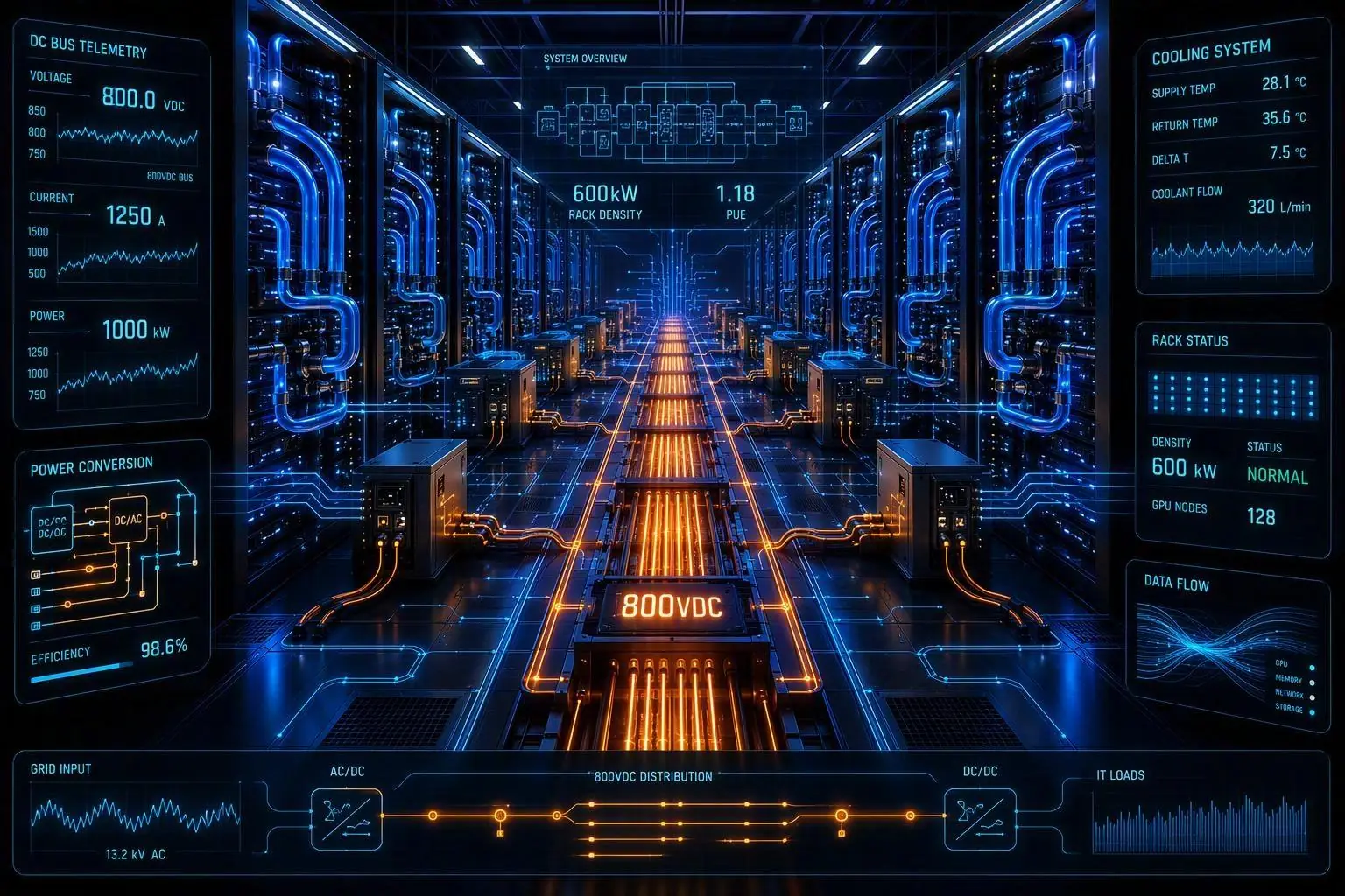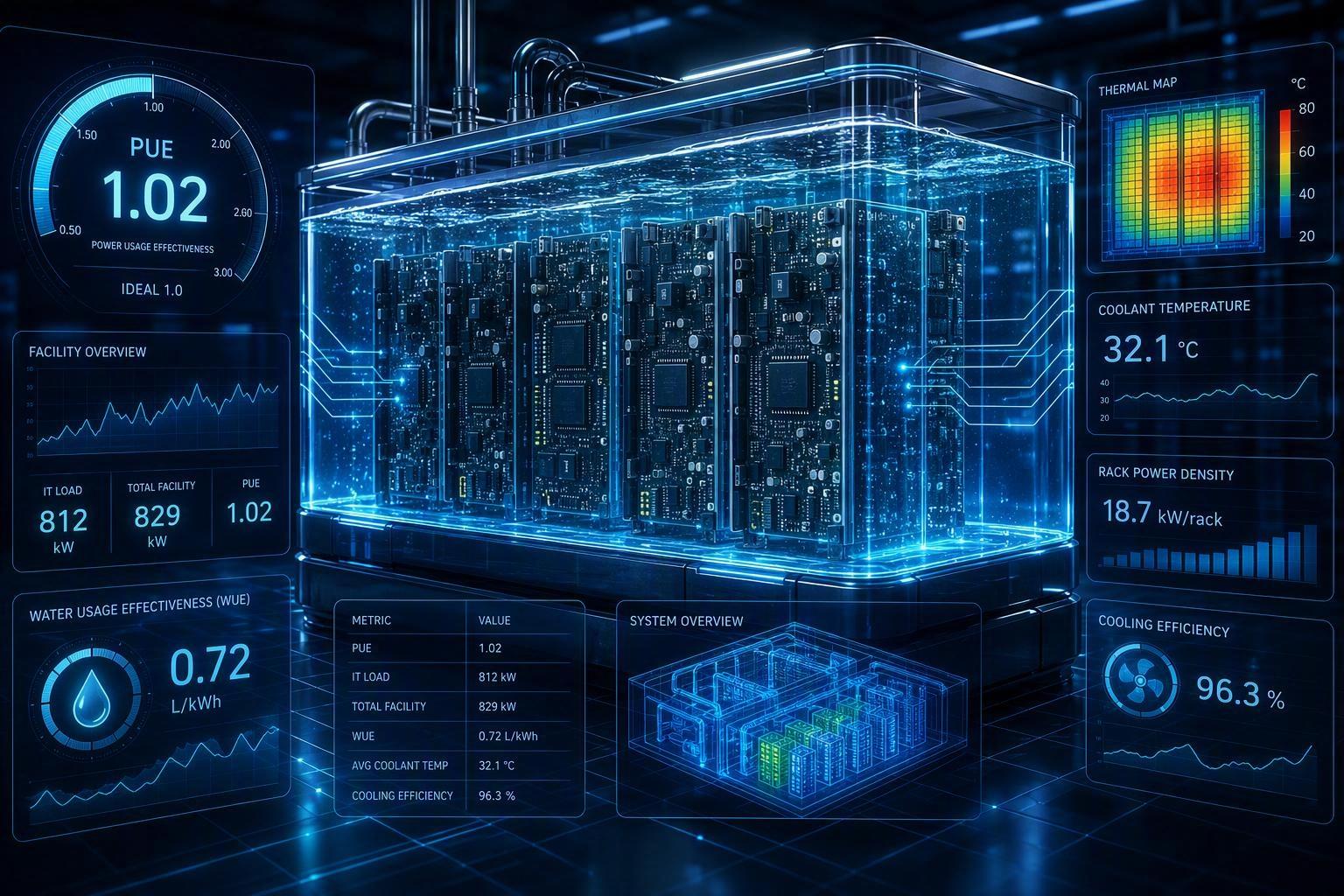
Key Takeaway: Deploying high-density AI clusters exceeding 40 kW to 100 kW per rack demands a thermal transition from conventional perimeter air conditioning to hybrid liquid-plus-air cooling topologies. Decoupling the Technology Cooling System (TCS) from the Facility Water System (FWS) using prefabricated Coolant Distribution Unit (CDU) skids enables facility operators to achieve design PUE below 1.20, maintain near-zero operational WUE using closed-loop dry coolers, and fulfill mandatory ASHRAE 90.4 and EU EED compliance requirements.
Table of Contents
ToggleIntroduction
Why AI data center cooling is different
Next-generation AI accelerators and GPU clusters present thermal characteristics fundamentally distinct from legacy cloud compute workloads. Individual server nodes now draw between 10 kW and 20 kW, pushing rack thermal densities from traditional 10–15 kW baselines to 40 kW, 80 kW, and beyond 120 kW per enclosure. At these power densities, air physics reaches a hard operational boundary. The volumetric heat capacity of air requires extreme airflow velocities, leading to unacceptable fan power penalties, severe rack-level temperature gradients, and acoustic levels that exceed occupational limits.
Direct-to-chip liquid cooling addresses this bottleneck by bringing fluid with roughly 3,500 times the volumetric heat capacity of air directly to the processor cold plates. Thermal management is no longer an ambient room conditioning problem; it is a precision hydraulic and thermodynamic transport process.
Your goals: density, uptime, efficiency
Project directors and facility engineering teams managing AI deployments must balance three competing mandates:
Power and spatial density: Maximize compute capacity per square meter without incurring localized thermal throttling or hot-spot shutdowns.
Deterministic uptime: Maintain Tier III/IV concurrent maintainability standards across all hydraulic, mechanical, and electrical boundaries.
Resource efficiency: Minimize Power Usage Effectiveness (PUE) and Water Usage Effectiveness (WUE) to lower Total Cost of Ownership (TCO) while meeting strict regional environmental compliance rules.
Achieving these goals simultaneously requires moving away from custom field-built mechanical plants toward standardized, factory-tested modular cooling infrastructure.
How hybrid liquid-plus-air cuts PUE and WUE
A hybrid cooling strategy combines direct liquid cooling (DLC) cold plates for high-heat components (GPUs, CPUs, optical transceivers) with targeted air cooling for ambient rack components (memory modules, power supply units, motherboards). Typically, liquid loops capture 70% to 85% of total rack thermal output, leaving the remaining 15% to 30% to low-velocity air systems.
This hybrid approach slashes facility energy and water footprints through two direct mechanisms:
Lowering PUE: Removing 80% of heat via liquid drastically reduces server fan speeds and eliminates energy-intensive compressor chillers. Facilities operate on economized warm-water loops, reducing mechanical cooling energy and driving overall PUE down from legacy averages of 1.5–1.8 to 1.12–1.20.
Lowering WUE: Liquid-to-air dry coolers operating with warm fluid supply temperatures (30°C to 45°C) can reject heat to ambient outdoor air without evaporative water consumption. This enables zero operational water loss in normal conditions, pushing site WUE to near 0.00 L/kWh.
Reference architecture
Hybrid topology overview
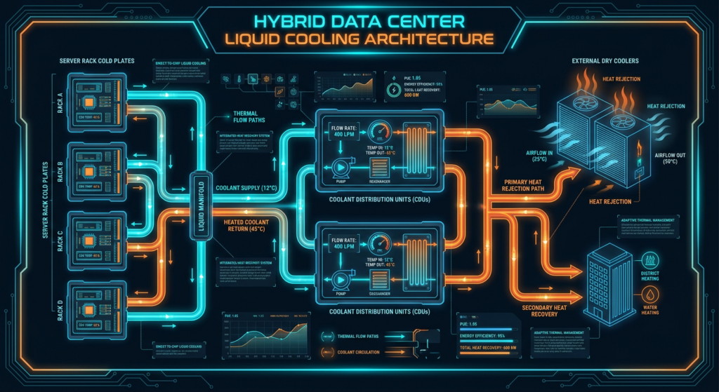
The baseline reference architecture for an AI data center hall integrates three primary fluid loops working in heat-exchange sequence: the Technology Cooling System (TCS) inside the IT rack, the secondary Coolant Distribution Unit (CDU) fluid loop, and the primary Facility Water System (FWS) connecting to external rejection equipment.
GPU / CPU Cold Plates → TCS Secondary Loop (CDU) → FWS Primary Loop → External Dry Coolers
Air conditioning for residual heat relies on low-EC (Electronically Commutated) fan wall arrays or rear-door heat exchangers (RDHx) tied to the same FWS temperature regime, avoiding separate low-temperature chilled water systems.
IT loop vs facility loop boundaries
A strict physical and operational boundary must separate the internal IT cooling circuit from the external facility infrastructure:
Technology Cooling System (TCS) / IT Loop: Operates entirely within the white space. It circulates ultra-pure fluid (deionized water with glycol or dielectric fluid) through cold plates, manifolds, and blind-mate connectors. Operating pressures stay tightly controlled between 140 kPa and 350 kPa to minimize mechanical stress on micro-channel cold plates.
Facility Water System (FWS) / Facility Loop: Operates between the CDU heat exchanger and outdoor heat rejection equipment. It uses standard treated industrial water and runs at higher operating pressures (300 kPa to 600 kPa).
Separating these loops ensures that raw facility water never enters server cold plates, preventing scaling, biofouling, and catastrophic volume spills inside the server room.
Thermally segmented AI zones
High-density AI halls benefit from thermal zoning based on compute density. Racks housing standard cloud storage or microservices run on low-density air cooling, while AI training clusters operate in dedicated high-density liquid zones.
By segmenting the hall, operators can supply higher coolant temperatures (ASHRAE W32 to W45 classes) directly to the GPU racks while supplying moderate temperatures to air-cooled zones, optimizing hydraulic pumping energy across the entire facility.
Liquid loop design
Coolant spec and qualification
Fluid chemistry management inside the TCS loop is essential to maintain long-term heat transfer efficiency and prevent galvanic corrosion:
Fluid selection: Inhibited Propylene Glycol (PG25/PG30) or ultra-pure deionized water with organic corrosion inhibitors and biocides.
Electrical conductivity: Maintained at or below 100 µS/cm to prevent electrical tracking during minor fluid weeping.
Wetted materials compliance: All wetted metals must consist of nickel-plated copper, stainless steel (316L), or EPDM/FKM elastomers. Aluminum and bare brass must be strictly prohibited in the TCS loop to prevent galvanic degradation.
CDUs, manifolds, and quick disconnects
The CDU acts as the operational heart of the liquid loop. Liquid-to-liquid CDUs incorporate plate heat exchangers, redundant variable-speed circulating pumps, micro-filtration assemblies (25 to 50 micron), and integrated expansion tanks.
Distribution manifolds mounted within or beside the rack split fluid flow evenly across multiple cold plates. Manifold connections utilize stainless-steel Quick Disconnects (QDs) equipped with flat-face, non-drip flush valves. Non-drip couplings ensure zero spillage during server insertion, removal, or maintenance activities under pressure.
Pro Tip: Always select Quick Disconnects certified under ISO 16028 standards with double-shutoff valves and confirm flow coefficient (Cv) values to keep rack pressure drops under 35 kPa at maximum flow.
Serviceability and leak containment
Because fluid flows within millimeters of high-voltage silicon, multi-barrier leak containment strategies are mandatory:
Negative pressure operation: Operating secondary loops under slight vacuum or low positive pressure reduces the physical driving force for external leaks.
Drip trays and point sensing: Stainless-steel catchment trays lined with continuous sensing cables run beneath all rack manifolds, CDU skids, and overhead piping runs.
Automated isolation valves: Sensing cables trigger fast-acting motorized ball valves at the CDU manifold interface, isolating fluid lines within milliseconds of moisture detection.
Efficiency and metrics
Designing for low PUE and stable WUE
Evaluating energy and water efficiency requires precise mathematical tracking across seasonal climate variations.
Power Usage Effectiveness (PUE) is defined as:
PUE = Total Facility Energy / IT Equipment Energy
In a liquid-cooled AI facility, chillerless operation with dry coolers keeps non-IT load limited to low-power CDU pumps and dry cooler fans, driving annual average PUE to between 1.12 and 1.18.
Water Usage Effectiveness (WUE) measures on-site operational water consumption:
WUE = Annual Water Usage (Liters) / IT Equipment Energy (kWh)
By using closed-loop dry coolers instead of open evaporative cooling towers, facilities eliminate evaporation, blowdown discharge, and drift losses, achieving a WUE of 0.00 to 0.05 L/kWh.
Warm-water and heat reuse (ERF)
ASHRAE TC 9.9 guidelines define liquid cooling classes based on facility water supply temperatures:
Cooling Class | FWS Supply Temp (°C) | Heat Rejection Technology | Heat Reuse Potential |
|---|---|---|---|
W17 / W27 | 17°C – 27°C | Refrigeration Chillers / Economizers | Low (Low Delta-T) |
W32 / W40 | 32°C – 40°C | Dry Coolers (100% Free Cooling) | Moderate (District heating, greenhouse) |
W45 / W+ | 45°C + | High-Temp Dry Coolers | High (High-grade industrial waste heat) |
Operating at W40 or W45 allows fluid returning from cold plates to exceed 50°C to 55°C. This high-grade waste heat can be exported to district heating networks or industrial processes, improving the facility’s Energy Reuse Factor (ERF):
ERF = Reused Energy / Total Facility Energy
90.4 compliance and telemetry
Navigating regulatory requirements mandates compliance with recognized energy standards. Under the ASHRAE Standard 90.4-2022 performance framework, data centers must demonstrate that facility infrastructure does not exceed maximum allowable Mechanical Load Component (MLC) and Electrical Loss Component (ELC) thresholds specified for their target climate zone.
Furthermore, European data centers with IT capacity exceeding 500 kW face mandatory reporting under the EU Energy Efficiency Directive (EED). Real-time telemetry must log and publish monthly PUE, WUE, ERF, and temperature metrics via automated Modbus/BACnet sensors tied to the building management system.
Reliability and controls
N+1 and 2N boundaries
To maintain Tier III/IV compliance without ballooning capital expenditure, hydraulic redundancy must be applied at key system boundaries:
CDU Pumping: N+1 or N+2 dual-head canned motor pumps within each CDU skid.
Facility Distribution Piping: Dual-header ring mains or dual-riser (2N) pipe routing equipped with manual and automatic isolation valves.
Heat Rejection: N+1 dry cooler fan modules with independent power feeds.
Instrumentation and digital twins
Modern liquid cooling circuits require dense sensor arrays operating at high sample rates (1 Hz to 10 Hz):
Ultrasonic flow meters at CDU supply and return lines.
Differential pressure transmitters across cold plates and heat exchangers.
Dual-redundant RTD temperature sensors on supply and return headers.
Integrating these sensor streams into a real-time digital twin allows physics-based modeling of hydraulic pressure curves. The digital twin predicts fluid degradation, pinpoints minor line restrictions before thermal throttling occurs, and dynamically adjusts pump speeds to match instantaneous GPU power draw.
Fault isolation and maintenance under load
Under full compute load, hot-swapping pumps, filters, or CDU modules requires automated bypass control. When a pump fault occurs, check valves prevent backflow while the secondary pump automatically ramps up within 200 milliseconds, ensuring fluid flow through cold plates remains uninterrupted.
⚠️ Warning: Never attempt hot-swapping secondary loop filter cartridges without verifying that the manual bypass loop is fully engaged and pressure differential across the filter housing is depressurized below 10 kPa.
Modular delivery and schedule
Prefab plants and skid strategies
Constructing liquid-cooled mechanical plants on-site leads to severe trade coordination issues, quality control variance, and site labor congestion. Transitioning to factory-prefabricated modular cooling skids shifts up to 80% of piping, electrical, and control assembly work to off-site manufacturing facilities.
Integrated manufacturers like Coolnetpower engineer containerized and skid-mounted liquid cooling solutions—including pre-wired CDUs, expansion loops, filtration banks, and smart control panels—built and pressure-tested under factory conditions.
Factory Skid Assembly → Pressure & Leak Testing (Hydro/N2) → Site Rigging → Plug-and-Play Hookup
Benefits of prefabricated skids include:
ISO 9001 quality control with automated orbital welding and x-ray pipe joint inspection.
Factory Acceptance Testing (FAT) with real thermal dummy loads prior to site dispatch.
Up to 40% reduction in total field construction time.
Long-lead items and phasing
Equipment procurement schedules represent the primary critical path risk in data center delivery. Coolant distribution units, custom dry coolers, and high-flow pumps often carry factory lead times of 30 to 50 weeks.
Adopting a phased modular strategy aligns capital expenditure directly with server deployment ramps:
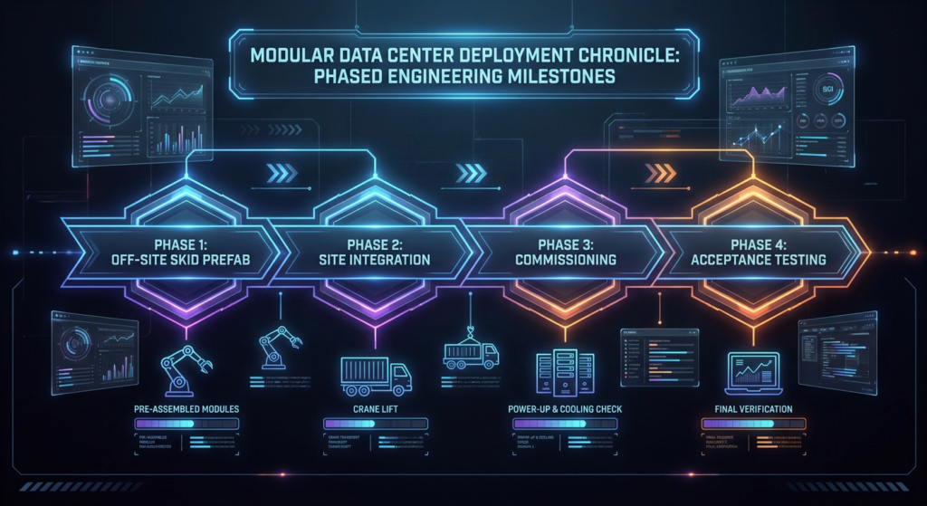
Phase 1 (Base Building): Install main FWS headers, primary electrical distribution, and structural pads for dry coolers.
Phase 2 (Skid Arrival): Rig and connect pre-tested CDU skids as compute capacity is added.
Phase 3 (Rack Integration): Connect fluid manifolds via flexible hoses as server racks are racked and stacked.
Commissioning and acceptance tests
Commissioning liquid cooling systems follows a rigorous five-level (Level 1 to Level 5) testing protocol:
Level 1 & 2: Factory acceptance testing and equipment static checks.
Level 3: Hydrostatic pressure testing (1.5 times operating pressure for 24 hours) and nitrogen purging.
Level 4: Functional system testing utilizing electrical thermal dummy load banks to verify CDU speed control, fault failover, and leak isolation response.
Level 5: Integrated systems testing (IST) simulating total utility power loss, generator transfer, and full thermal load shedding.
Conclusion
Key decisions to lock early
Lowering PUE and WUE in AI data centers requires locking four foundational architectural decisions during conceptual design:
Cooling Topology Selection: Establish direct liquid cooling ratio (e.g., 80% liquid / 20% air) based on GPU roadmap power densities.
Fluid Operating Temperature Class: Select ASHRAE TC 9.9 target class (e.g., W32 or W40) to enable 100% dry cooling free-cooling operation.
Loop Separation Boundary: Standardize liquid-to-liquid CDUs as the strict separation barrier between TCS and FWS loops.
Delivery Method: Choose off-site prefabricated skids to eliminate field piping errors and compress delivery schedules.
How to track PUE, WUE, and ERF
Sustained efficiency demands automated metric tracking:
Install revenue-grade power meters (Class 0.2s) at IT power distribution units and total facility utility inputs.
Deploy inline ultrasonic heat meters on both TCS and FWS loops to calculate real-time thermal rejection rates.
Connect BMS telemetry to automated reporting dashboards aligned with ASHRAE 90.4 MLC models and EU EED regulatory reporting templates.
Next steps for retrofit vs new build
For New Builds: Implement a fully optimized warm-water hybrid architecture with dry coolers from day one. Design floor loading to support 1,500–2,500 kg per rack footprint and integrate overhead pipe racking for fluid manifolds.
For Retrofits: Audit existing floor loading and power capacity. Deploy modular CDU skids into existing white spaces and convert legacy CRAH/CRAC units into secondary air-handling loops or rear-door heat exchangers to support hybrid high-density pods without halting ongoing operations.