Table of Contents
ToggleIntroduction
If you’ve ever reviewed a “2N” or “N+1” power design and still felt uneasy about the real-world failure modes, you’re not alone. In most incidents, the root cause isn’t that a UPS was undersized on paper—it’s that the interfaces between systems weren’t designed, commissioned, or operated as a single end-to-end power path.
That’s why UPS PDU integration matters: it turns a collection of individually “redundant” components into a power chain that is actually maintainable, testable, and resilient under stress.
At a high level, the end-to-end path looks like this:
Utility and/or generator sources
Transfer/switching and distribution
UPS (with appropriate bypass)
PDU(s) (facility or row-level and/or rack PDUs)
Rack distribution (dual feeds)
In resilient designs, this entire chain is built as dual A/B feeds—two distinct power paths intended to survive a component failure or planned maintenance event without dropping IT load.
Standards and codes shape how these systems are specified and operated:
TIA-942-C for data center infrastructure topology and redundancy planning
NEC (NFPA 70) for compliant electrical installation
NFPA 70E and IEEE 1584 for arc-flash risk assessment, labeling, and safe work practices
UL 1778 (UPS) and UL 1008 (transfer switches)
IEEE 519 for harmonic distortion and power quality expectations
The goal isn’t to turn an article into a code book. It’s to make sure your architecture and day-2 operations don’t violate the basics.
Redundancy topologies
Power-path discussions often start at the topology label, but project outcomes depend on whether the distribution layer is designed and documented as part of the same system. If you need background on common distribution building blocks, see Coolnetpower’s power distribution systems for data centers.
N, N+1, 2N overview
Redundancy labels are useful, but only if you translate them into “what happens when something is out of service.”
N: Exactly enough capacity for the expected load. Any single failure or maintenance event can become an outage.
N+1: One extra module/unit beyond what’s required. This supports many concurrently maintainable designs—if (and only if) the rest of the path is also designed to allow isolation.
2N: Two fully independent capacity trains. Each train is capable of carrying the full critical load. This is the classic foundation for resilient A/B power paths.
A practical test for any topology claim is simple:
Key Takeaway: The topology label only matters if you can remove any single component (for maintenance or failure) and the remaining path still carries the load.
Dual A/B at the rack
In most colocation and enterprise facilities, the rack is where redundancy is either realized—or quietly defeated.
A true dual A/B rack implementation typically requires:
Dual-corded IT equipment (dual PSUs), with one cord on PDU A and the other on PDU B
Separate upstream protection so a single breaker trip can’t drop both feeds
Rack-level documentation that maps outlets to upstream circuits and panels
The most common “looks redundant but isn’t” mistakes include:
Both cords plugged into the same rack PDU (or same upstream branch circuit)
A and B PDUs fed from the same upstream panelboard
A/B paths sharing a single transfer device that becomes a new single point of failure
Physical separation rules
Physical separation is where theory meets construction reality. “A and B are separate” should mean more than different label colors.
For colo build-outs, separation discipline usually includes:
Separate raceways/paths where feasible (so a single cut, crush, or water event can’t take both)
Separate distribution boards and protective devices
Separation in rooms and rows where practical (not always possible in small footprints, but the intent matters)
The deeper point is risk-based: if one event can reasonably impact both paths, you don’t have redundancy—you have two failure opportunities.
Sizing and load balance (UPS PDU integration)
This section is where UPS PDU integration becomes measurable: you are turning load assumptions into ratings, branch circuits, and phase allocations that still work during failover.
UPS and PDU ratings
Integration starts with making sure the “handshake” between UPS output and PDU input is engineered, not assumed.
Key checks:
kW vs kVA alignment: UPS output capability, PDU ratings, and the nature of the IT load (power factor, crest factor, and non-linear behavior) should be understood early.
Voltage and phase compatibility: The UPS output configuration must match what the downstream PDUs expect.
Short-circuit and interrupting considerations: Your protective devices must be appropriate for the system’s available fault current and coordination plan.
Also separate two different ideas:
Capacity (can it carry the load?)
Maintainability (can you isolate and service it while the load stays up?)
A design can be “big enough” and still fragile if the bypass/maintenance path isn’t integrated.
Three-phase balancing
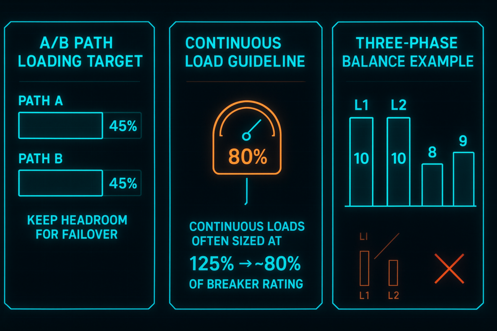
Three-phase balance isn’t just an efficiency detail. In high-availability environments, imbalance can trigger nuisance trips, hot neutrals, and unexpected capacity limits.
At the PDU and rack-PDU layer, aim to:
Distribute single-phase loads across L1/L2/L3 as evenly as practical
Treat phase balance as a commissioning deliverable (measured, not assumed)
Re-check after large moves/adds (especially GPU rows or storage refreshes)
If you want a pragmatic reference when explaining continuous load practices to stakeholders, the “80% rule” is often cited as a shorthand. A more precise explanation is that continuous-load sizing commonly uses the 125% convention, which is why designers talk about ~80% loading on standard-rated breakers—device listing and 100%-rated assemblies can change the exact limit. For a clear discussion of the concepts, see IAEI’s overview on continuous-load sizing and 80% vs 100% rated breakers and Schneider Electric’s explanation on 80% vs 100% rated circuit breakers.
High-density racks
High-density racks amplify every integration weakness:
More load per rack means less margin for error in A/B allocation
Rapid load swings can expose monitoring blind spots
Harmonics and power quality become more material at scale (this is where IEEE 519 becomes a useful reference point for design discussions)
A common resilience practice in dual-path designs is to operate each path well below its maximum so it can absorb a full failover. Many teams target roughly 40–50% per path under normal operation—not as a law, but as a planning heuristic that preserves headroom for a path loss and reduces surprise overloads. (For an overview discussion of data center distribution topologies and normal loading practices, see DEI Power’s article on data center power distribution design.)
Transfer and bypass
UPS topology choice
UPS topology is a design decision that affects not only efficiency, but failure behavior and bypass strategy.
At an awareness level, what matters most is that you can explain (and test) answers to questions like:
What happens to the load if the UPS experiences an internal fault?
What is the bypass source, and how is it protected?
Can the UPS be maintained without exposing the load to an unprotected raw source longer than intended?
If the design goal is concurrent maintainability, the UPS topology must be matched to an operational plan that includes switching procedures and test windows.
STS/ATS coordination
In many facilities, reliability depends on transfer equipment behaving exactly as expected—especially during generator events or maintenance operations.
Two coordination principles help avoid surprises:
Avoid creating a new single point of failure: A single shared transfer device can undermine an otherwise redundant A/B architecture.
Coordinate timing and sources: Ensure the alternate source is actually available before relying on a transfer sequence, and verify behavior under realistic conditions.
If you specify transfer switching, confirm it is appropriately listed—UL 1008 is the relevant standard for transfer switches—while UPS equipment is generally evaluated under UL 1778.
Maintenance bypass
Maintenance bypass is where “integrated design” becomes operational reality.
A good bypass strategy supports these outcomes:
A component can be isolated and serviced without dropping load
Bypass switching steps are documented, trained, and repeatable
Bypass does not silently turn your design into “N” during maintenance
⚠️ Warning: The highest-risk moment in a redundant design is often a maintenance window when one path is intentionally impaired. Treat bypass procedures as part of the architecture, not a field afterthought.
Monitoring and telemetry
This is where intelligent PDU monitoring and UPS telemetry stop being “nice-to-have” and become a resilience control: they turn A/B symmetry, breaker limits, and battery risk into visible, actionable signals.
Intelligent PDU metrics
Intelligent PDUs are not just about “seeing amps.” They help you operate a dual-path design the way it was intended.
High-value metrics include:
Per-outlet or branch circuit current (depending on PDU type)
Voltage and power (kW/kVA) by feed
Circuit breaker status (where supported)
Local environmental context (rack inlet temperature/humidity where deployed)
The key is to make A/B symmetry visible: which path is trending higher, where phase imbalance is growing, and which racks are approaching practical limits.
UPS battery analytics
Battery is still where many UPS incidents become outages. Awareness-stage diligence means you can answer:
What is the condition of the battery string(s) today?
Are you tracking alarms/events over time, not just real-time status?
Is battery monitoring integrated into the same operational view as PDU load and transfer events?
DCIM/BMS integration
The integration question isn’t whether you have a DCIM or BMS—it’s whether the data is actionable.
A useful integration typically brings together:
UPS alarms, load, runtime estimates, and event logs
PDU load by path/phase and breaker/circuit status
Transfer events (ATS/STS) and generator run status (where applicable)
Coolnetpower’s DCIM and power monitoring (UPS/PDU/battery) supports unified visibility across UPS, power distribution, and battery monitoring, helping operators spot A/B imbalance and act before trips.
Safety and compliance
NEC and UL listings
Compliance has two practical meanings for project directors:
Equipment is correctly selected and installed for the application.
Maintenance and change control can happen without improvisation.
In the US, NEC (NFPA 70) is the baseline for how electrical systems are installed and protected. For equipment selection, listings matter: UPS equipment is typically evaluated under UL 1778, and transfer switches under UL 1008.
Arc-flash and coordination
Even the best redundant topology fails if the safety program prevents timely maintenance—or if maintenance is done unsafely.
NFPA 70E focuses on safe work practices for electrical equipment, and IEEE 1584 is widely used for arc-flash incident-energy calculations.
Arc-flash labeling is a practical requirement for many facilities. For background on what labels commonly include (voltage, boundary, and PPE/incident-energy information), see Vertiv’s discussion in Understanding 2015 Changes to NFPA 70E.
Protection coordination is also part of the safety story: selective coordination reduces unnecessary upstream trips that can take down more load than the fault itself.
Grounding and labeling
Grounding and labeling are boring—until they aren’t.
In A/B environments, disciplined labeling and documentation reduce “human-caused single points of failure,” such as:
moving a rack from A to B without updating schedules
swapping cords during maintenance and defeating redundancy
misidentifying upstream source during an outage response
Treat labeling, one-lines, and rack-level power maps as controlled documents with change management.
Conclusion
UPS–PDU integration is less about buying “more redundant equipment” and more about making the dual A/B power paths real end to end—from source to UPS to PDU to rack.
Key takeaways:
Redundancy labels (N, N+1, 2N) only matter when the full chain can be isolated and tested without dropping load.
Rack-level implementation (dual cords, correct upstream feeds, clean documentation) is where most “paper redundancy” fails.
Sizing is an integration problem: align ratings, preserve failover headroom, and actively manage three-phase balance.
Transfer and bypass are architecture, not accessories—test them like you test the UPS.
Monitoring turns design intent into operational reality by making A/B symmetry, breaker constraints, and battery health visible.
Next steps that reduce risk quickly:
Perform a failure-mode walk-through on the one-line: “what happens if this device is out?”
Commission and document A-path-loss and B-path-loss tests (in controlled windows).
Run periodic drills so maintenance bypass and transfer procedures are routine, not heroic.
If you’d like, we can review your one-line and produce a procurement-friendly commissioning checklist (A/B mapping, bypass steps, and telemetry points) before construction starts.