
Data halls
Rear-door-cooled data center
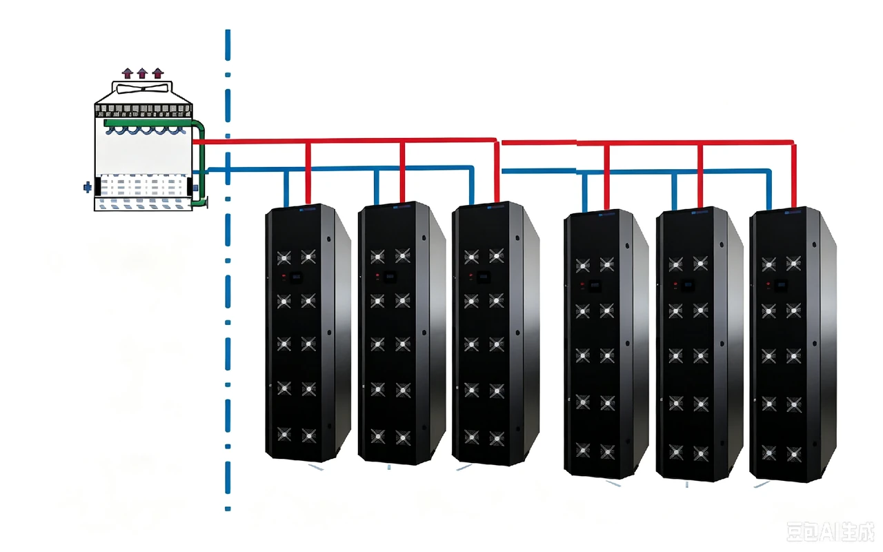
Rear-door heat exchangers remove heat at each rack exhaust, supporting higher-density air-cooled computing rows.
- Cooling approach
- Heat-pipe rear-door heat exchangers
- Deployment
- High-density single rack rows
- Solution planning range
- Up to 60 kW per rack
Overview
Collect heat at the rack exhaust
Rear-door heat exchangers place the cooling interface at the server exhaust. The rack terminals connect to a shared outdoor heat-pipe system.
Rack interface
Fit the heat exchanger to the rack
Check the rack dimensions, exhaust airflow, door movement and access for connections and maintenance.
Shared outdoor plant
Coordinate the terminal network
Design the rack connections, pipe routes and outdoor-unit capacity around the combined thermal load.
Site conditions
Define duty and standby operation
Select the operating modes and redundancy for the site's ambient conditions and continuity requirements.
Reference configuration
A forty-rack high-density layout
The reference case uses 58 kW per rack within the 60 kW solution envelope. The listed heat load is the combined rack load.
In this example
- Per rack in this example
- 58 kW
- IT racks
- 40
- Total heat load
- 2,320 kW
Scroll the table to see all columns
| Equipment | Model | Quantity | Duty / standby |
|---|---|---|---|
| Rear-door heat exchanger | HPX060D | 40 | One per rack |
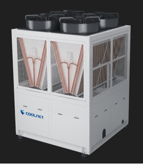
| Multi-connected outdoor unit | CNQXF500 | 5 | 4 + 1 |
Duty + standby: 2 + 1 means two duty units and one standby unit.
This example is not a fixed bill of materials. Final equipment selection, capacity and redundancy depend on the IT requirements and site operating conditions.
Technology
Inside the system
Collect heat at the rear of each rack
A single row of server racks connects to heat-pipe rear-door precision cooling and ceiling-suspended multi-split outdoor units. Refrigerant-pump free cooling reduces reliance on compressor operation when outdoor conditions allow.
- The solution envelope supports up to 60 kW per rack; the reference layout uses 58 kW per rack.
- Forty HPX060D rear-door units serve the 40-rack reference layout.
- Five CNQXF500 outdoor units operate in a 4 + 1 reference arrangement. A separate duty/standby arrangement for the rear-door units is not specified.
Three operating modes, one outdoor unit
The modular outdoor unit combines a variable-frequency compressor and refrigerant pump. Its dual-loop controls automatically switch between three modes and prioritize natural cooling when outdoor conditions allow.
- An independent natural-cooling coil supports operation in low outdoor temperatures.
- Oil-free terminals support long piping routes and large installation height differences; allowable limits require equipment selection.
- The self-developed intelligent controller includes fault self-diagnosis.
- Reference performance: room-temperature fluctuation below ±2 °C with the fully variable-frequency design, and more than 30% outdoor-unit footprint saving through integration.
| Mode | Cooling method |
|---|---|
| Natural cooling | Fully variable-frequency refrigerant-pump operation |
| Hybrid cooling | Variable-frequency refrigerant pump and compressor operating together |
| Compressor cooling | Fully variable-frequency compressor operation |
Five terminal formats for different layouts
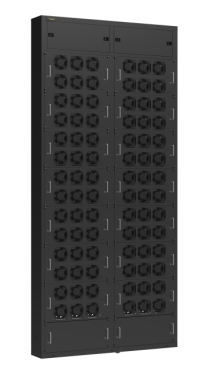
Five heat-pipe terminal formats serve different rack layouts and air-distribution paths within the multi-split platform.
Related equipment
Explore the product families
Plan your project
Start with your requirements
Share your deployment needs to discuss the right configuration.
Talk to our teamUseful details to include
- Rack dimensions, exhaust airflow and heat load at each rack
- Rear-door access, connection details and pipe routing
- Outdoor-unit selection at site conditions and required standby capacity