
Containerized systems
Liquid-cooled container data center
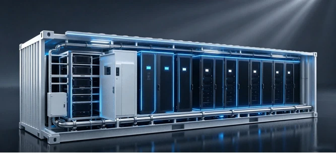
A prefabricated container integrates liquid-cooled racks, CDUs and residual air cooling, with outdoor dry coolers.
- Cooling approach
- CDUs, dry coolers and residual air cooling
- Deployment
- Prefabricated computing containers
- Solution planning range
- 100 kW+ per cabinet
Overview
Integrate the module and its site interfaces
Liquid-cooled computing cabinets, CDUs and supporting air cooling share a prefabricated enclosure. Outdoor dry coolers and site utility connections complete the system.
Computing enclosure
Coordinate the container layout
Arrange computing and network cabinets with the CDU, supporting cooling and service access.
Liquid interfaces
Connect the rack and facility circuits
Define the secondary pipework, coolant requirements and primary-side connections to the dry coolers.
Air-side heat
Provide residual air cooling
Select in-row cooling for the portion of the rack heat released into the enclosure air.
Site installation
Plan delivery and connections
Confirm the foundation, lifting route, utility interfaces and maintenance clearances before delivery.
Reference configuration
A six-cabinet B300 container
B300 reference configuration with six computing cabinets and two network cabinets, one active and one standby.
In this example
- Per computing cabinet
- 105 kW
- Computing cabinets
- 6
- Network cabinets · 1 active + 1 standby
- 2
| Source field | Source value |
|---|---|
| IT Rack Qty | 48 |
The source lists IT Rack Qty as 48 separately from six computing cabinets. It does not define the counting basis for this field; 48 is retained as printed and is not interpreted as a server count.
Refrigerant-pump in-row PAC units remove the residual air-side heat load.
Scroll the table to see all columns
| Equipment | Model | Quantity | Duty / standby |
|---|---|---|---|
| Coolant distribution unit | HP-CDU600R | 2 | 1 + 1 |
| Residual air cooling | CLA60F | 4 | 3 + 1 |
| Outdoor dry cooler | HP-DC300 | 3 | 2 + 1 |
Duty + standby: 2 + 1 means two duty units and one standby unit.
Reference water temperatures
Confirm final setpoints with the selected servers and site conditions.
- Primary facility circuit
- 35–45 °C
- Secondary rack circuit
- 40–50 °C
This example is not a fixed bill of materials. Final equipment selection, capacity and redundancy depend on the IT requirements and site operating conditions.
Technology
Inside the system
Designed for factory integration and staged growth
Prefabricated delivery brings the computing enclosure, cooling and power together before the module arrives on site. Standardized manufacturing and complete system integration support shorter construction cycles and flexible expansion.
- Pre-install and test the integrated systems at the factory.
- Coordinate module manufacturing with civil works and utility preparation.
- Use repeatable modules for staged capacity expansion.
- Confirm transport, lifting, external connections and final commissioning as part of the delivery plan.
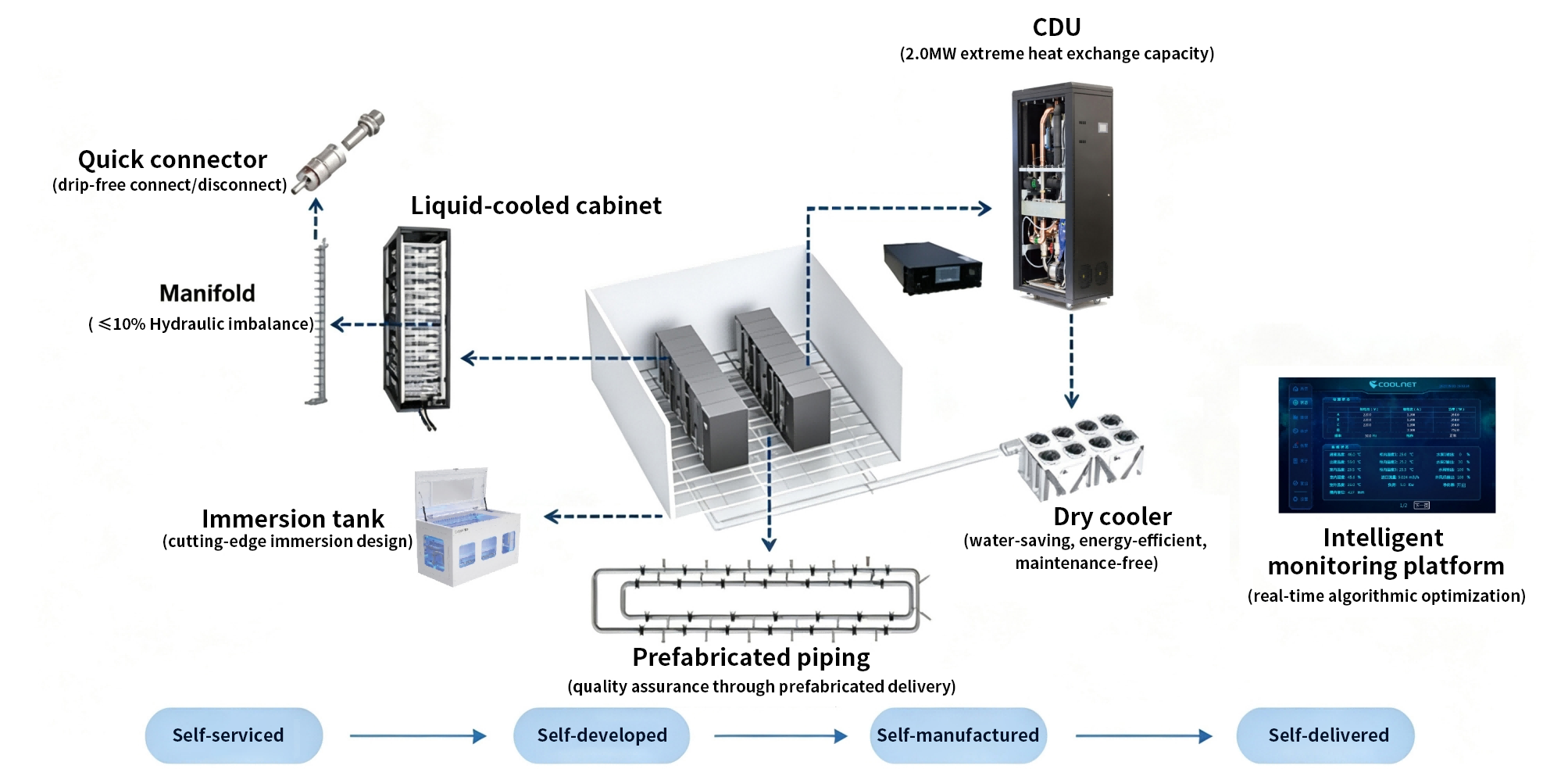
The complete liquid-cooling equipment chain
The portfolio connects rack-level liquid cooling to coolant distribution, outdoor heat rejection and system monitoring. It includes both cabinet and immersion approaches; the reference configurations on this page use liquid-cooled cabinets.
- In-house service, development, manufacturing and delivery support the complete equipment chain.
| Component | Function and reference capability |
|---|---|
| Quick connectors | Drip-free connection and disconnection |
| Manifolds | Distribute coolant to the rack; reference hydraulic imbalance ≤10% |
| Liquid-cooled cabinets | House the rack-level liquid-cooling connections |
| Coolant distribution units | Transfer heat between rack and facility circuits; portfolio reference capability of 2.0 MW heat exchange |
| Immersion tanks | An alternative immersion-cooling format within the portfolio |
| Dry coolers | Outdoor heat rejection designed for water saving and energy efficiency |
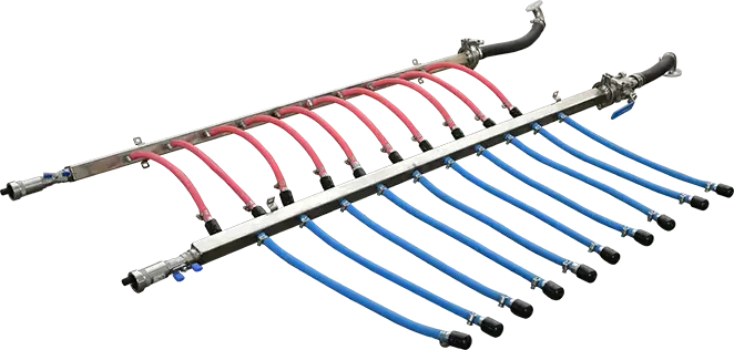
| Prefabricated piping | Factory-prepared pipework for delivery and quality control |
| Intelligent monitoring | Real-time monitoring and algorithm-based optimization |
Primary cooling and secondary rack circuits
The architecture separates the primary cooling-source arrangement from the secondary cold-plate arrangement. Both modular-room and container deployments use these distinct parts of the cooling system.
- Primary cooling-source arrangement — dry cooler, liquid-cooling CDU and dual-source fan wall.
- Secondary cold-plate arrangement — liquid-cooled cabinets and prefabricated pipework.
- The project configuration determines the selected equipment, interfaces, water temperatures and residual air-cooling provision.
Related equipment
Explore the product families
Plan your project
Start with your requirements
Share your deployment needs to discuss the right configuration.
Talk to our teamUseful details to include
- Required computing load, server selection and container layout
- Foundation, transport route, lifting access and service clearances
- Site power, pipework routes, ambient conditions and dry-cooler placement
- Coolant specification, operating temperatures and monitoring requirements