Table of Contents
ToggleKey takeaways
CRAC vs CRAH in one line: CRAC typically means DX (refrigerant + compressor) cooling; CRAH typically means chilled-water coil cooling fed by a central plant.
Use the “~200 kW pivot” as a planning heuristic, not a rule: below ~200 kW, DX/CRAC is often simpler; above ~200 kW, chilled-water/CRAH can be easier to scale—if you already have (or can justify) a chilled-water plant.
Air management beats nameplates: containment, airflow path discipline, and fan control often decide whether you hit stable inlet temps and a good PUE.
Redundancy is a system choice: “N+1” at the unit level doesn’t help if your distribution path (power, piping, controls) is a single point of failure.
Future-proofing is about rack density: plan a hybrid path (room-based air + close-coupled air + selective liquid) before densities force a rushed retrofit.
Introduction
You will learn how CRAC vs CRAH differ and which fits your room—and how to avoid common server room cooling pitfalls.
Who this is for: facility, IT, and data center leaders in the U.S.
What you’ll get: clear thresholds, efficiency tips, and a selection path.
How to use it: apply the steps to your site, load, and goals.
CRAC vs CRAH basics
How CRAC works (DX)
A CRAC (Computer Room Air Conditioner) is typically a direct expansion (DX) precision air conditioning system: it uses a refrigerant circuit (with a compressor) to absorb heat from return air and reject that heat outdoors (via a condenser/heat rejection system).
If you’re evaluating options for a server room, this “self-contained” nature is often the point: DX systems can be deployed without building a full chilled-water plant.
Coolnetpower’s own server-room explainer describes CRAC in this common DX sense: refrigerant cycle + compressor, purpose-built for close control in IT spaces (precision cooling right for your server room).
How CRAH works (chilled water)
A CRAH (Computer Room Air Handler) is typically an air handler that cools air by passing it over a chilled-water coil. Instead of generating cooling inside the unit, it transfers heat to chilled water supplied by a central plant.
Practically, that means the CRAH choice is really an infrastructure choice: you need the chilled-water plant (chillers or equivalent), pumps, piping, valves, controls, and a heat rejection method.
Coolnetpower summarizes CRAH in this common chilled-water sense in the same server-room guide (precision cooling right for your server room).
Key differences at a glance
Dimension | CRAC (DX) | CRAH (Chilled water) | What it means in the field |
|---|---|---|---|
Cooling “source” | Refrigeration happens locally in/near the unit | Cooling comes from a central plant | CRAC is often faster to deploy; CRAH is often easier to scale once the plant exists |
On-site infrastructure | Condenser/heat rejection + refrigerant management | Chillers, pumps, piping, valves, water treatment | CRAH shifts complexity into the plant and distribution loop |
Efficiency at scale | Can be fine in small rooms; distributed compressors can add overhead | Often stronger at scale, especially with good plant design | CRAH tends to shine when you’re optimizing annualized energy |
Maintenance profile | Refrigerant circuit + compressors are a major maintenance domain | Fans, coils, valves + plant coordination | Different skill sets and spares strategy |
For a deeper “room-based vs close-coupled” comparison (which often matters more than the CRAC/CRAH label), Coolnetpower lays out decision criteria in its guide on CRAC/CRAH vs InRow cooling for server rooms.
Fit by size and load
Small rooms and edge sites
Small rooms and edge sites usually share three constraints:
You need cooling quickly (deployment and commissioning timelines matter).
You may not have chilled water available in a reliable, maintainable way.
Loads are moderate and grow in steps, not as a single multi-megawatt jump.
In these conditions, CRAC/DX is often selected because the infrastructure burden is lower. But the bigger “gotcha” in small rooms isn’t DX vs chilled water—it’s airflow geometry: short-circuiting, recirculation, and hot spots caused by poor return paths.
If you’re trying to keep room-based cooling viable, Coolnetpower’s sizing guide is a useful starting point for load math and airflow estimation (size air conditioning systems for server rooms).
Large halls and campuses
As you move into large halls or campus expansions, two things typically change:
You can justify (or already have) central plant investment.
You care more about system-wide efficiency, fault domains, and lifecycle serviceability than “how fast can we place units.”
This is where CRAH systems (fed by chilled water) often fit better—especially if your program values standardization across multiple phases and buildings.
The ~200 kW pivot
A common planning heuristic is the ~200 kW IT load pivot:
Below ~200 kW of IT load, CRAC/DX is often the simpler, more economical way to get predictable cooling.
At and above ~200 kW, CRAH/chilled water often becomes more cost-effective and scalable—particularly when you already have (or can justify) the chilled-water plant.
Dataspan frames this threshold explicitly in its comparison of CRAC vs. CRAH cooling units.
Two cautions (important for project leaders):
Total kW isn’t the whole story. A 120 kW room with uneven rack density and weak containment can be harder to cool than a 250 kW room with disciplined airflow.
Chilled water only helps if the plant and distribution are designed for your real operating modes. If the plant is poorly staged or sensors are sparse, you can still end up overcooling—or chasing instability.
Efficiency and controls
Economizers and VFD fans
If you’re trying to improve PUE, the most dependable path usually isn’t swapping “CRAC vs CRAH” first—it’s reducing the hours and power spent moving and mechanically chilling air.
Two levers show up repeatedly:
Economizers (free cooling): using outdoor conditions (air-side or water-side) to reduce mechanical refrigeration hours.
Variable-speed fans (VFD/EC): modulating airflow to match real demand instead of running fans at a fixed, conservative speed.
ENERGY STAR notes that better air management reduces mixing, enables slower fan speeds, and supports more economizer hours; its hot aisle/cold aisle layout guidance cites measurable cooling savings when mixing is reduced.
Coolnetpower also frames “airflow/containment → setpoints → economizer-first controls → metering” as a practical roadmap in its free cooling roadmap to lower PUE.
Setpoints and ASHRAE TC 9.9
A useful way to keep setpoint decisions grounded is to treat server inlet conditions as the governing metric.
ASHRAE’s thermal guidance (TC 9.9) is widely used as an operating envelope reference for data processing environments; the ASHRAE Thermal Guidelines reference card is a helpful high-level summary.
Practical implications for operators:
Measure where it matters: don’t run your program off a single wall sensor.
Raise temperatures carefully: setpoint changes should be tied to inlet stability (and alarms), not just “save energy.”
Treat humidity/dew point as part of the control loop: it’s easy to add unintended risk when economizer hours rise.
Containment and airflow
Containment is the fastest way to make either CRAC or CRAH behave like “precision” cooling.
It reduces supply/return mixing.
It increases the usable temperature differential across the room.
It stabilizes server inlet temperatures and reduces hot spots.
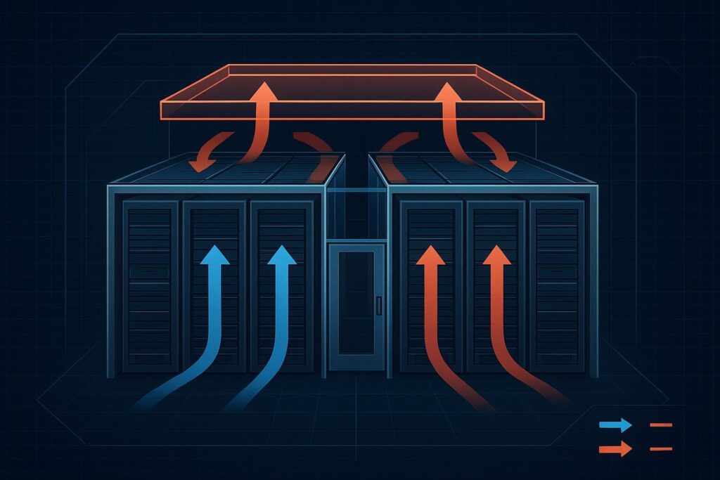
ENERGY STAR’s hot aisle/cold aisle layout guidance ties containment-style air management to both energy savings and improved airflow effectiveness.
Key Takeaway: If you’re missing inlet stability today, start with airflow discipline (containment + return path + pressure management) before adding capacity.
Reliability and TCO
Redundancy patterns (N+1/2N)
“Redundancy” gets discussed as a unit count, but the risk you’re managing is loss of cooling capacity to the IT load—which can happen via unit failure or distribution failure.
A practical shorthand:
N: exactly enough capacity to meet design load. No spare.
N+1: one extra unit beyond what’s required.
2N: two independent systems, each capable of carrying the full load.
Vertiv provides a clear overview of how these patterns work in cooling systems in its explainer on N+1 redundancy for cooling.
For project leaders, the key question is: where is your real single point of failure?
CRAC-heavy designs can concentrate risk in power feeds and heat rejection.
CRAH-heavy designs can concentrate risk in chilled-water distribution and plant dependencies.
Maintenance and skill requirements
TCO is often dominated by what you need to keep in-house (or under contract):
CRAC/DX: compressor health, refrigerant circuit maintenance, leak management, condenser/heat rejection service.
CRAH/chilled water: valve and actuator maintenance, coil hygiene, pump upkeep, water treatment, sensor calibration, and plant controls coordination.
Neither is inherently “easier.” The winning option is usually the one that matches your organization’s maintenance model and spares strategy.
Refrigerant shifts and DX fleets
If you operate a DX fleet, the refrigerant transition is a real lifecycle consideration.
In the U.S., the phasedown of high-GWP HFCs is driven by federal policy (AIM Act and EPA rules). The EPA HFC phasedown FAQs are a practical starting point, and ACEEE provides broader context in its overview of U.S. low-GWP refrigerant regulations.
What that means operationally (in plain terms):
Plan for future equipment refresh cycles and parts availability.
Treat leak management as both a cost and compliance practice.
Avoid assumptions that every legacy unit can be “simply retrofitted” to a new refrigerant.
Selection checklist

Use this checklist as a short internal design review before you talk to vendors.
If CRAC fits you
CRAC/DX is usually a fit when most of these are true:
You don’t have a reliable chilled-water plant available for the room.
Your IT load is below ~200 kW or your growth happens in small, modular steps.
You need a faster deployment path with less plant design work.
Your team is more comfortable maintaining refrigerant-based equipment than a chilled-water plant.
To avoid common failure modes, pair CRAC with:
disciplined hot/cold aisle layout
containment where feasible
variable-speed fan control and a sensor strategy based on inlet temperatures
Coolnetpower’s discussion of room-based vs close-coupled options is a good cross-check when you have mixed rack densities (CRAC/CRAH vs InRow cooling for server rooms).
If CRAH fits you
CRAH/chilled water is usually a fit when most of these are true:
You already have chilled water (or a campus program where plant investment makes sense).
Your program is trending above ~200 kW and needs predictable scaling.
You want to optimize annualized energy, including economizer hours.
You have an operations model that can handle plant-level maintenance and controls.
If you’re planning the chilled-water path, treat distribution as a first-class design problem (valves, sensors, isolation, and fault domains), not an afterthought.
Plan for hybrid liquid cooling
Even if this article is about air-based precision cooling, most project leaders are now forced to plan for a second reality: rack density is becoming a design driver.
A practical, low-risk planning approach is to design for hybrid cooling:
Keep room-based precision air (CRAC or CRAH) as the baseline for “standard” racks.
Add close-coupled solutions or selective liquid for the few rows/pods that exceed your air-cooling comfort zone.
Coolnetpower’s retrofit-oriented comparison lays out one phased path—rear-door heat exchangers and in-row options for targeted density, and direct-to-chip as a longer-term answer for sustained high-density pods (rear‑door vs in‑row vs direct‑to‑chip retrofit comparison).
Where Coolnetpower’s experience shows up in practice is in the integration work that makes hybrid cooling livable:
aligning airflow design, containment, and controls so the “air side” stays stable
planning liquid loops and isolation so maintenance doesn’t become a downtime event
coordinating cooling with power distribution and monitoring so you can verify performance after commissioning
If you want examples of the baseline equipment categories involved (without committing to a design yet), see Coolnetpower precision air conditioning.
Conclusion
Use the load threshold, infrastructure, and growth plan to choose confidently.
Prioritize containment, VFD fans, and optimized setpoints to lower PUE.
Roadmap for liquid cooling where densities rise to future-proof your design.
If you want a low-friction next step, start by copying the checklist above into your internal design review and validating it against your rack density map and expansion plan. If you need a commissioning-oriented checklist for sensor placement and setpoint governance, Coolnetpower’s team can share a technical fit guide based on your room constraints.