Introduction
A fan wall cooling system (sometimes called a thermal wall, or described as thermal wall cooling in some technical literature) is a perimeter-based air handling approach that uses large arrays of high-efficiency fans—often paired with chilled-water coils—to deliver uniform supply air to an entire hyperscale data hall. Instead of distributing many smaller CRAC/CRAH units across the white space (or relying on a raised-floor plenum), the “air-moving engine” is concentrated into a wall or mechanical gallery and controlled as a system.
Hyperscale operators adopt fan walls because they scale cleanly with 5–10MW+ halls, simplify airflow management in slab-floor designs, and can reduce fan energy through variable-speed control and low static-pressure distribution when containment and leakage control are done well. For a foundational overview of the fan-wall concept and use cases, see Legrand’s explainer on fan wall cooling advantages and challenges.
In this guide, you’ll learn:
The core architecture: components, control loops, and how fan walls fit into hyperscale halls
The measurable benefits and where the benefits can be overstated
Practical design and integration practices for 2025–2026
A clear comparison with CRAC/CRAH across energy, airflow risk, redundancy, and footprint
How to think about AI/HPC and hybrid liquid-cooling readiness without “painting yourself into a corner”
A roadmap and checklist for implementation and commissioning
This is written for:
Data center designers and consultants
Facility engineering and operations leaders
Sustainability teams tracking PUE/WUE and water constraints
Procurement leaders who need a defendable evaluation framework
What a fan wall cooling system is
Core architecture and components
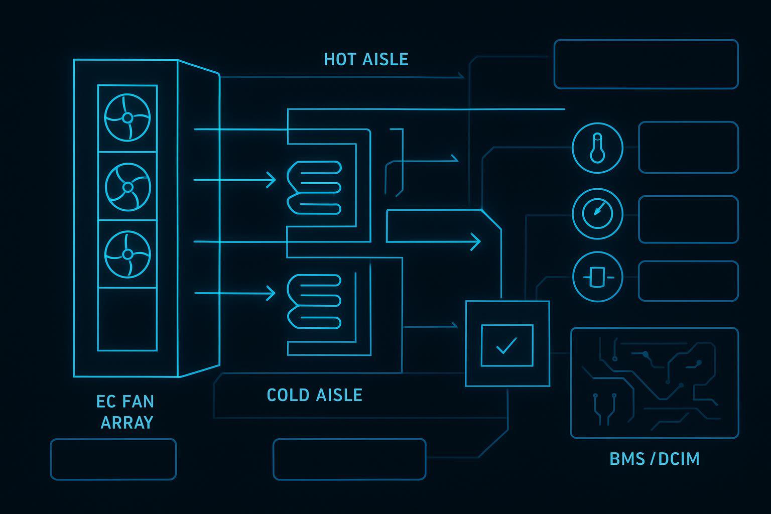
A fan wall cooling system is, at its core, a large air handler broken into modular “cells.” Most hyperscale implementations use:
A fan array (commonly EC fans) that can be controlled as a group or by module
A cooling section (often chilled-water coils) that removes sensible heat from recirculating return air
Filtration and service access designed for high uptime operations
A supply path that feeds cold aisles (typically with containment) at low static pressure
A return path that captures hot exhaust air back to the wall (via ceiling return, hot-aisle return, or a mechanical gallery)
In practice, what many people mean by “fan wall cooling data center” is this perimeter array approach paired with a disciplined aisle/containment strategy—so the entire hall behaves like a predictable air-distribution system, not a collection of local cooling zones.
A helpful vendor-level description of the building blocks is Trane’s overview of Fan Coil Wall for Data Centers, which outlines the fan-array + chilled-water coil concept and the “blow-through” air-handling arrangement common in these systems.
Two practical implications for hyperscale halls:
Capacity is delivered as an array, not a single point. This supports uniformity and resilience, but it also means airflow and control design must be treated as a system-level problem.
The hall becomes a low-pressure duct. The containment strategy and leakage management determine whether you realize the intended fan-power savings.
Controls and redundancy fundamentals
In hyperscale, fan-wall controls typically use a combination of:
Static pressure or differential pressure (to ensure enough pressure at the cold aisle / plenum boundary)
Supply air temperature (SAT) targets, often reset dynamically
Return air temperature (RAT) and humidity constraints
Valve control on chilled-water coils (where applicable)
Fan-speed coordination across modules to prevent hunting and reduce acoustic/mechanical stress
Redundancy is usually achieved by design patterns such as:
Fan-level redundancy (losing one fan cell doesn’t collapse airflow)
Module-level redundancy (N+1 at the air-handler/module level)
Control and power segmentation so that a single breaker/UPS/ATS failure does not take down the wall
The subtle point: redundancy isn’t only about “how many fans.” It’s about how quickly the system can recover airflow and stable inlet temperatures after a fault—and whether your monitoring can detect the early degradation before it becomes a hot-spot event.
Where fan walls fit in hyperscale halls
Fan walls most commonly appear in:
Slab-floor hyperscale halls that avoid raised floors
Hot-aisle or cold-aisle contained layouts where the supply/return boundary is enforced
Mechanical gallery designs that separate service access (gray space) from IT white space
Fan walls most commonly appear in hyperscale data center cooling programs where building architecture supports:
predictable supply-air delivery
controlled return-air capture
serviceability without disrupting IT rows
Measurable benefits for hyperscale
Energy, PUE and water impacts
A fan wall cooling system can improve energy performance primarily through fan-power reduction and better “system control” at partial load.
Where the savings typically come from:
Variable-speed EC fans that track demand rather than running at constant speed
Lower static pressure distribution compared to designs that depend on long underfloor paths or poorly controlled bypass
Higher chilled-water temperatures and economization hours when the plant is designed for it
However, PUE and water outcomes are not inherent to “fan wall” as a label. They depend on the whole chain: containment leakage, supply/return temperatures, water-side design, and controls.
For an efficiency-first framing that emphasizes reducing mixing, using variable speed drives, and designing the mechanical system as a whole, the U.S. DOE’s Best Practices Guide for Energy-Efficient Data Center Design (Revised 2024) is a useful reference.
Key Takeaway: A fan wall doesn’t automatically deliver a lower PUE. It enables lower fan energy if you maintain clean pressure boundaries and run the plant at efficient setpoints.
On the water side: fan wall air systems can be paired with different heat rejection strategies. If water scarcity and permitting are constraints, teams often prioritize designs that minimize evaporative dependence and maximize economization hours where climate permits.
Airflow uniformity and space recovery
Uniform airflow is a primary reason hyperscalers use fan walls. With an appropriately designed array, the goal is to reduce:
cold-aisle temperature stratification
row-to-row pressure variation
local hot spots caused by bypass and recirculation
A second benefit is space recovery:
less cooling equipment occupying white space
fewer “obstructions” in the IT area
flexibility in row layout as long as containment and return paths remain intact
The caution: uniformity is “earned,” not assumed. If containment is partial, if tile/ceiling leakage is unmanaged, or if the return-air path is poorly defined, the hall behaves like a leaky duct network—and airflow will follow the leaks.
Serviceability, resilience and MTTR
Fan walls can reduce maintenance burden and MTTR because:
service access can be concentrated in the mechanical gallery
fan cells/modules can be swapped without taking the entire hall offline
alarms and trending can be standardized across a repeating array
Resilience improves when you pair the physical modularity with:
clear failure-mode testing during commissioning
a monitoring strategy that detects degradation (not only hard faults)
The operational point procurement teams should care about: your maintenance model becomes more predictable when the hall uses fewer equipment “types” and repeating modules.
Design and integration best practices (2025–2026)
Airflow, containment and last‑rack delivery
In 2025–2026, the baseline best practice is not “hot aisle vs cold aisle” as a debate—it’s hot aisle containment (or cold-aisle containment, where that fits your layout) plus leakage control as a system.
Design practices that matter most:
Pick a containment strategy you can enforce operationally. Doors left open, missing blanking panels, and unsealed floor penetrations can erase fan-energy gains.
Design for pressure stability, not just average temperature. Differential pressure and aisle pressure stability help prevent recirculation at the worst racks.
Treat the rack as part of the cooling system. Cable cutouts, brush grommets, and blanking panels are often the cheapest “capacity” you can buy.
For a containment-focused overview that emphasizes cabinet-level sealing as the first line of defense, see Chatsworth’s Data Center Containment guide (2026).
Chilled‑water plant, coils and setpoints
A fan wall is only as efficient as the plant and setpoints that feed it.
Practical guidance:
Raise temperatures intentionally, within equipment limits. The performance lever is often higher supply air and higher chilled-water temperatures (where feasible), which improves chiller efficiency and increases economizer hours.
Use setpoint resets that follow real constraints. Reset strategies should be governed by rack inlet temperatures, humidity/dew point boundaries, and control stability—not by room averages.
Don’t trade efficiency for hidden risk. If a tighter band is required for certain AI/HPC islands, segment them and control them explicitly rather than forcing the entire hall into tight setpoints.
For an authoritative best-practices baseline, the U.S. DOE/FEMP/NREL 2024 design guide emphasizes minimizing mixing losses, applying variable-speed drives, and optimizing plant operation.
Controls, power and monitoring
At hyperscale, fan-wall success is largely a controls and instrumentation story.
Controls practices that reduce risk:
Coordinate control loops across air and water. Fan speed, coil valve position, pump speed, and plant supply temperature should be designed to converge—not fight.
Use multi-sensor control inputs. Combine aisle/rack inlet temperatures, differential pressure, and return air conditions so you don’t optimize one metric while violating another.
Design for degraded mode. Define how the system behaves during partial fan-cell failure, sensor failures, or plant excursions.
Power and monitoring practices:
Segment electrical feeds (so one panel/UPS event doesn’t take down the wall)
Instrument what matters: rack inlet temps, ΔT across coils, differential pressure at the right boundaries, valve positions, and fan-cell health
Tie alarms to action (what do operators do in the first 2 minutes, 20 minutes, and 2 hours?)
This “integrated design” mindset—treating power, cooling, and controls as one system—aligns with ASHRAE’s framing for AI facilities in its Integrated Design Principles.
Comparison with CRAC/CRAH
Energy efficiency and PUE differences
A simple rule of thumb: in large, modern hyperscale halls, the energy-efficiency conversation tends to favor centralized, hydronic, variable-speed systems over distributed DX-based units.
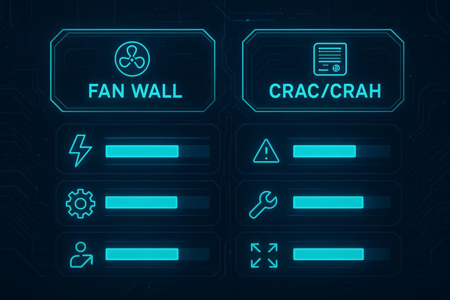
Quick framing many readers search for: CRAC vs CRAH vs fan wall comes down to whether cooling is delivered by distributed room units (CRAC/CRAH) or by a centralized wall/galleries that act as an air-handling backbone (fan wall), with plant-side choices (DX vs chilled water) and airflow discipline (containment/leakage control) driving most of the real-world outcome.
CRAC units (DX, compressor-based) can be practical for smaller or legacy spaces, but they are typically less efficient at hyperscale scale-up because each unit brings its own refrigeration cycle.
CRAH units (chilled water) can be efficient and are widely used, but they still distribute many units across the hall.
Fan wall systems concentrate air movement, can reduce static pressure requirements, and can be optimized as an array—especially at partial loads.
For baseline definitions of CRAC vs CRAH and where each fits, see Dataspan’s overview of CRAC vs. CRAH. For fan-wall architecture framing and trade-offs, Legrand’s explainer is a good starting point.
Airflow and hot‑spot risk
Hot-spot risk is usually less about the cooling “brand” and more about:
containment integrity
bypass/recirculation paths
control stability under partial load
whether your monitoring catches drift early
Fan walls can reduce hot-spot risk by improving uniformity, but they can also create blind spots if you rely on too few sensors or if the return path allows hot air to mix back into supply.
CRAC/CRAH layouts can work well when aisle design and tile management are disciplined—but in large halls, distributed units increase the number of local conditions you have to maintain.
Redundancy, maintenance and footprint
The comparison that matters operationally:
Redundancy: fan walls can be resilient at the fan-cell level, but only if the power segmentation and controls are designed for faults.
Maintenance: fan walls often simplify service access by moving work into the mechanical gallery.
Footprint: fan walls can free white space; distributed units consume white space and can constrain row layouts.
A vendor example of the thermal-wall concept and control emphasis is Mitsubishi Critical’s MEWALL cooling system, which illustrates how these systems are engineered around airflow uniformity and control.
AI/HPC and hybrid liquid‑cooling readiness
Rear‑door and direct‑to‑chip integration
As AI/HPC rack densities rise, many operators adopt a hybrid approach: air cooling remains responsible for “everything not on the cold plate,” while liquid cooling captures the dominant heat loads.
Two common integration paths:
Rear-door heat exchangers (RDHx) as a lower-disruption step that increases rack capacity without changing server internals. If you want a practical overview of chilled-water RDHx as a deployment option, see Coolnetpower’s chilled water rear door heat exchanger.
Direct-to-chip liquid cooling for sustained high-density AI/HPC. For a definitions-first explanation of cold plates, manifolds, and loop KPIs, Coolnetpower’s guide on direct-to-chip liquid cooling with cold plates is a good primer.
The design implication for fan walls: you still need robust airflow management for the residual heat, and you need containment/return paths that don’t break when certain rows become partially liquid-cooled.
Controls coordination to avoid demand fighting
Hybrid rooms often fail in subtle ways when air and liquid systems chase different targets.
Common “demand fighting” patterns:
The liquid loop is tuned to protect cold plates, while the air system is tuned to protect a room-average setpoint—so one loop constantly over-corrects.
A liquid-side restriction or CDU alarm causes a transient rise in outlet air temperature; the fan wall responds by ramping airflow, which masks the root problem and makes fault isolation harder.
Practical mitigation:
Define one thermal truth: rack inlet temperature bands and component limits, not room averages.
Make control ownership explicit: what is handled by IT telemetry vs BMS/DCIM.
Use coordinated reset logic so fan speed, coil valve position, and chilled-water supply temperature move together.
ASHRAE’s AI guidance emphasizes co-design and integrated thinking in its Energy and Thermal Efficiency resources.
From an integrated solutions provider perspective (and consistent with Coolnetpower’s approach of linking cooling, power, and monitoring under one delivery scope), the key is to treat hybrid air+liquid as a systems-integration program:
validate sensor placement and naming conventions early
define alarm-to-action playbooks (MOP/EOP) before go-live
run staged pilots that prove stability at partial load, not only at design load
Staged density growth and retrofit paths
A practical roadmap many hyperscalers follow:
Stage 1 (air-optimized): tighten containment, control leakage, optimize fan-wall control, raise setpoints conservatively within allowable equipment envelopes.
Stage 2 (hybrid bridge): deploy RDHx or targeted liquid for the highest-density rows; keep fan wall as the “backstop” for residual loads.
Stage 3 (liquid-forward): expand direct-to-chip coverage; re-tune fan-wall airflow targets to avoid oversupplying air (and wasting fan energy).
The planning advantage of an integrated portfolio is optionality: you can keep air-side infrastructure efficient while you add liquid capacity where density forces the issue. For a high-level overview of Coolnetpower’s broader integrated delivery scope (cooling + power + monitoring), see Coolnetpower integrated solutions.
Implementation roadmap and checklist
Site assessment, CFD and setpoint strategy
Start with an assessment that produces decisions, not just data:
Confirm current and target rack densities, row layouts, and containment strategy
Build a CFD and/or airflow model with realistic leakage assumptions
Define rack inlet temperature targets and acceptable excursions
Identify the control variables you will actually operate: fan speed targets, pressure setpoints, supply temperature resets
Checklist:
Containment type and enforcement plan documented
Leakage mitigation plan (blanking panels, grommets, sealing)
Sensor plan (rack inlet, DP, SAT/RAT, valve positions)
Setpoint reset logic drafted and reviewed by operations
Economization readiness and plant integration
Fan walls pair well with plant-side strategies that reduce compressor hours.
Checklist:
Plant supports efficient part-load operation (VFD pumps/fans where applicable)
Chilled-water temperature strategy defined (including summer/winter reset bounds)
Economizer sequence defined and tested (air-side or water-side, where used)
Water strategy clarified (WUE targets, water-risk constraints, reporting)
For practical planning inputs and estimation scaffolding, you can also use the Coolnetpower data center calculator to structure early-stage load and capacity assumptions.
Commissioning, testing and ongoing optimization
Commissioning should prove three things:
Thermal performance at the rack, not just room averages
Stability under partial load and transients (controls do not hunt)
Resilience under faults (degraded mode behavior is acceptable and documented)
Checklist:
Functional performance testing of fan-wall modules (including fan-cell failure scenarios)
Differential pressure validation across containment boundaries
Rack inlet temperature mapping under representative load patterns
Alarm thresholds tested, and MOP/EOP runbooks validated
Metering baseline established for PUE and WUE trending
Conclusion
Fan wall cooling systems are a strong fit for hyperscale data halls when you want a scalable, slab-floor-friendly architecture that can deliver uniform airflow and simplify service access—provided you treat containment, leakage control, controls, and plant integration as one system.
Immediate actions that typically de-risk a fan-wall program:
Build or update airflow/CFD models using realistic leakage assumptions
Tighten containment and last-rack delivery details (blanking, grommets, sealing)
Define setpoint and reset strategies that follow rack inlet limits, not room averages
Document a redundancy and degraded-mode plan that is testable during commissioning
Metrics to track as you operate and optimize:
PUE (trend by load band, not just annual average)
WUE (tie to economizer and heat rejection strategy)
Uptime and incident rates (including thermal alarms and near-miss hot spots)
Capacity headroom (airflow, coil capacity, pump/chiller limits, and control stability margins)
If you’re evaluating architectures across air and hybrid air+liquid, keep the decision grounded in integration risk and operational reality—not just nameplate efficiency claims.