Air cooling still works well for many rooms. But once you start packing more AI and HPC into each rack, you can hit a point where airflow becomes the constraint—not the IT.
Direct-to-chip (D2C) liquid cooling with cold plates is one of the most common ways operators solve that problem without fully immersing servers in fluid.
By the end of this beginner guide, you’ll be able to:
Name the four building blocks of a D2C system (cold plates, manifolds, CDUs, warm-water loops)
Explain the heat path in one sentence (chip → liquid → facility loop → heat rejection)
Read two core KPIs—ΔT and inlet temperature—without guessing
Table of Contents
ToggleWhat “direct-to-chip liquid cooling” means
Direct-to-chip liquid cooling (sometimes called “direct liquid cooling”) means you bring a controlled liquid coolant to the hottest components—usually CPUs and GPUs—using a cold plate that is physically attached to the chip package.
Instead of relying on room air to carry most of the heat away, the system uses a liquid loop to transport heat from the server to a coolant distribution unit (CDU) and then into the facility’s water loop for heat rejection.
If you want a broader overview of where this sits among other high-density options, see Coolnetpower’s guide on why liquid cooling is essential for high‑density data centers.
The four components you should recognize in any D2C design
In this guide, I’ll use one consistent set of terms:
Cold plate: chip-level heat exchanger
Manifold (liquid cooling manifold): rack-level distribution and return headers
CDU: pump/control + heat exchanger between IT loop and facility loop
Warm-water loop: the facility-side loop carrying heat to rejection/reuse
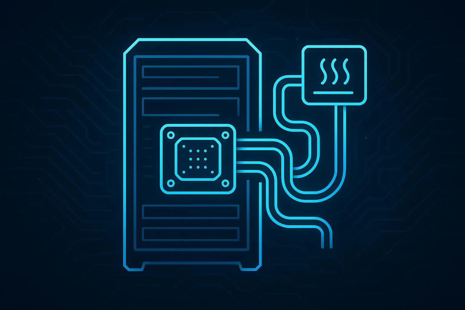
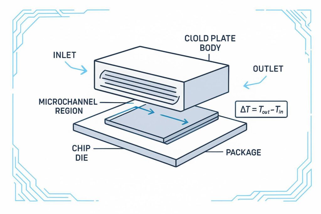
1) Cold plate (at the chip)
A cold plate is a metal heat exchanger that mounts onto a CPU or GPU package. Coolant flows through internal channels and picks up heat through the plate.
Beginner mental model: the cold plate is your “radiator,” but instead of air moving through fins, liquid moves through channels.
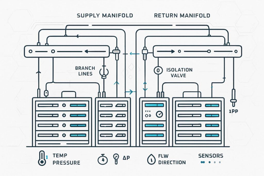
2) Manifold (distribution plumbing)
A manifold is the distribution layer—often at rack level—that splits the supply flow to multiple servers (or multiple cold plates per server) and collects the warm return flow.
Two terms you’ll see often:
Quick disconnects (QDs): connectors designed for serviceability (disconnect/reconnect without turning a maintenance task into a full drain-down).
Isolation valves: allow you to shut off a branch for maintenance.
Why manifolds matter: most “gotchas” in early D2C deployments aren’t about the cold plate itself—they’re about distribution (balancing flow, controlling pressure drop, and maintaining serviceability).
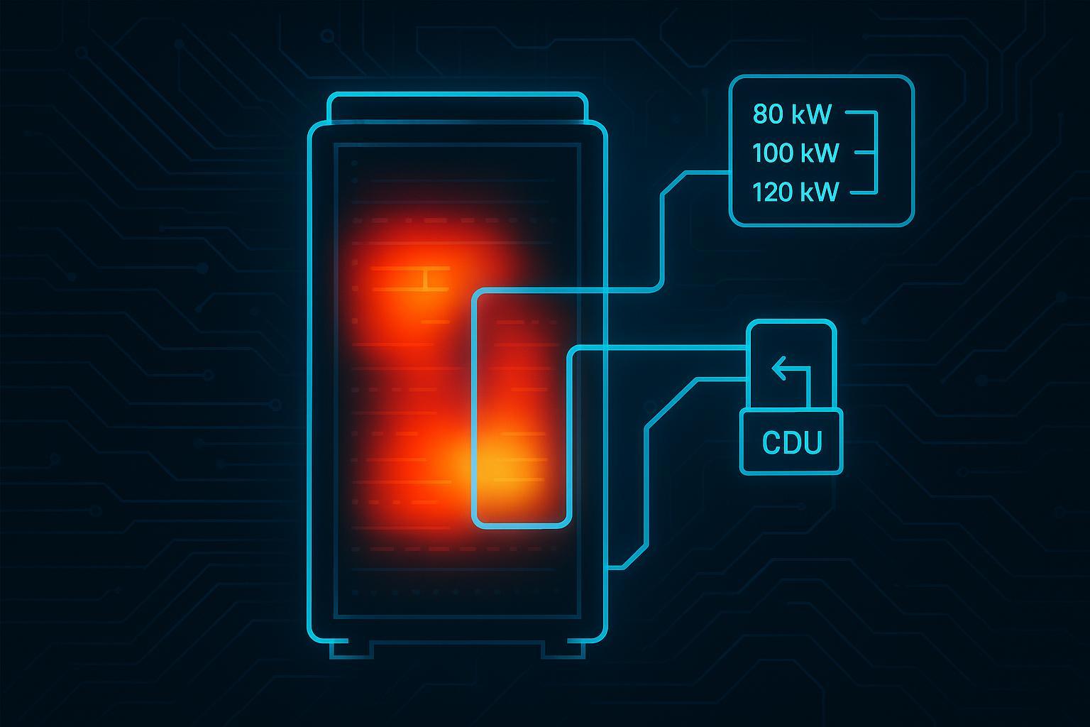
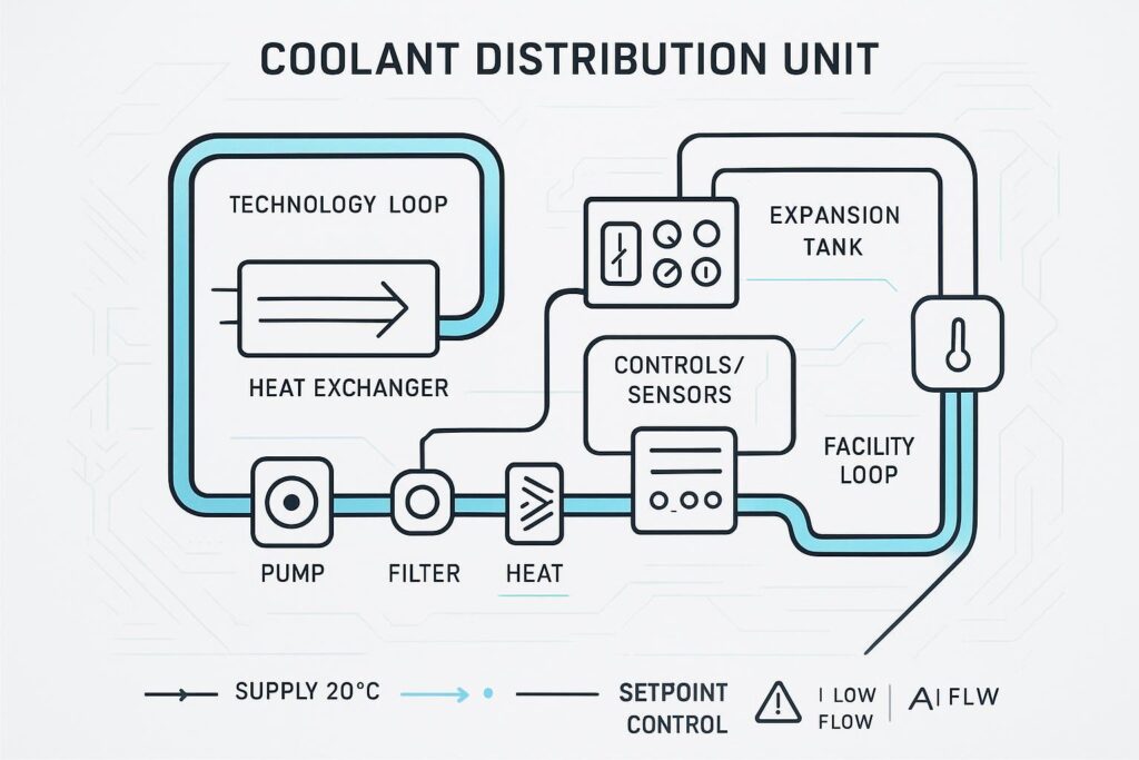
3) CDU (Coolant Distribution Unit)
A CDU is the piece that makes the technology loop behave like an engineered system instead of “some pipes with water in them.” In most architectures it:
pumps the technology loop
monitors temperature/pressure/flow
controls setpoints and alarms
uses a heat exchanger to move heat from the technology loop to a facility loop
For a clear overview of how direct-to-chip systems are typically described at a high level (including the CDU’s role), see Vertiv’s 2024 deep dive on direct-to-chip cooling.
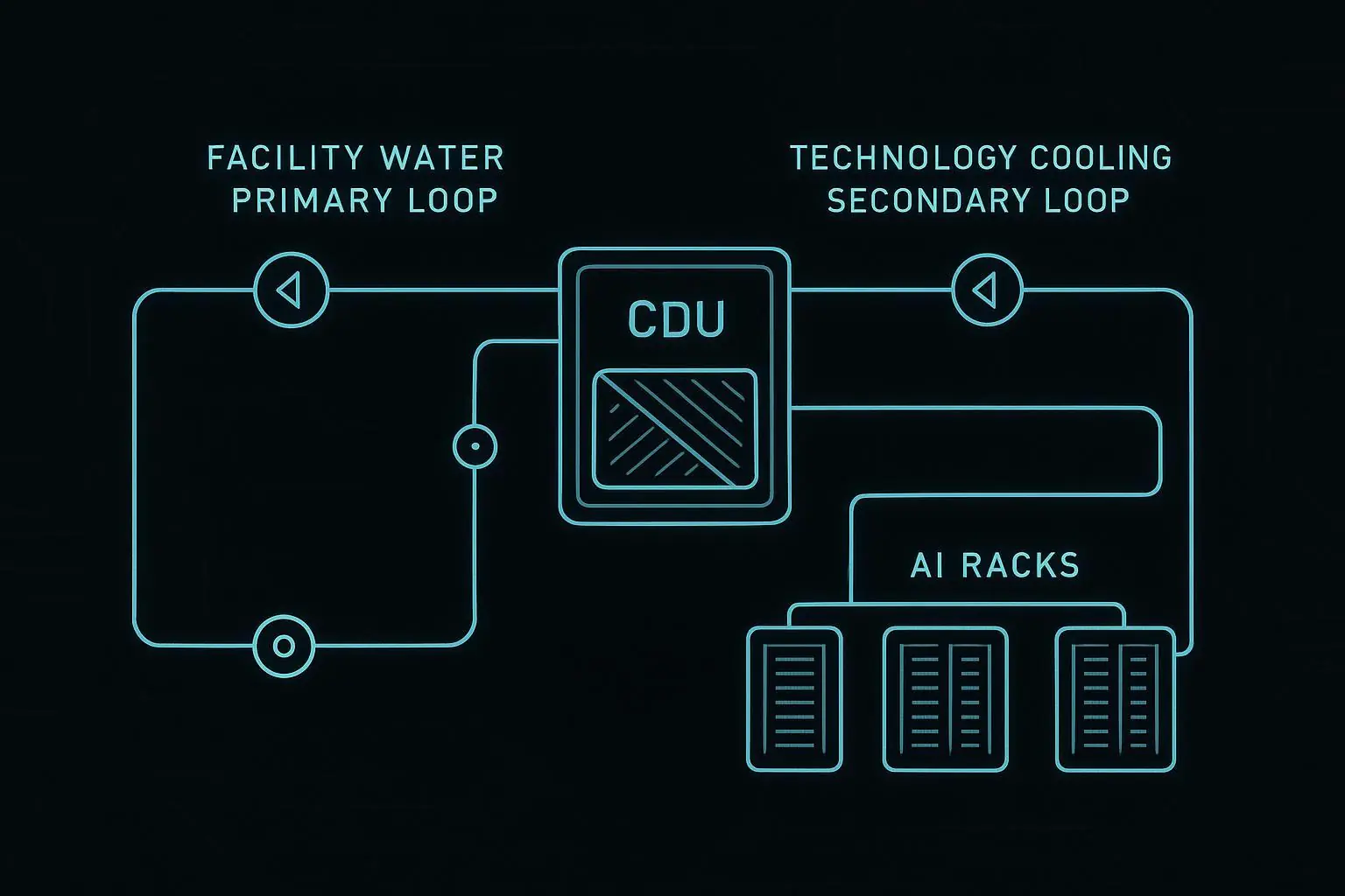
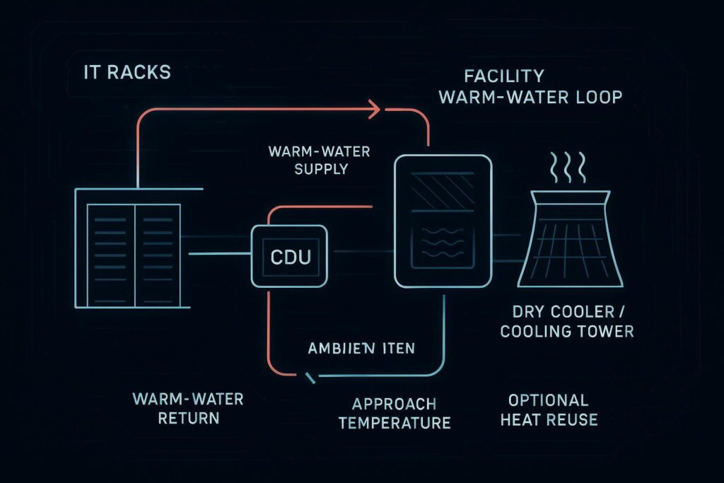
4) Warm-water loop (facility heat rejection)
The CDU doesn’t “destroy” heat—it transfers it. The facility side then carries that heat to a heat rejection system (dry cooler, cooling tower, etc.) or potentially to heat reuse.
In many designs, the facility loop can run “warm” compared to traditional chilled-water systems—one reason operators look at D2C as densities rise.
Key takeaway: In a D2C system, the cooling “architecture” is really the heat path: chip → cold plate → manifold → CDU → facility loop → heat rejection.
How warm-water D2C actually removes heat (step-by-step)
Supply coolant enters the rack (from the CDU) and flows into the supply manifold.
The manifold distributes flow to each server/cold plate branch.
In each cold plate, coolant absorbs heat and exits warmer.
Warm return coolant collects in the return manifold and goes back to the CDU.
The CDU transfers heat across a heat exchanger into the facility loop, then sends cooled supply back to the rack.
This is single-phase operation: the coolant stays liquid throughout.
The KPIs that matter first: ΔT and inlet temperature
Most teams look at dozens of signals. As a beginner, start with two that show up in almost every discussion:
KPI 1: ΔT (temperature rise)
ΔT is the temperature increase of the coolant across a component or loop segment.
Across a cold plate (or server branch): ΔT = T_out − T_in
Across a rack loop: ΔT = T_return − T_supply
ΔT is useful because it connects directly to heat movement:
Q = ṁ × C_p × ΔT
Where:
Q = heat moved (W)
ṁ = coolant mass flow rate
C_p = coolant specific heat
ΔT = temperature rise
This energy-balance relationship is foundational and commonly used when characterizing liquid heat removal.
How to read ΔT without fooling yourself
Big ΔT can be good (the fluid is carrying a lot of heat) or a warning (not enough flow).
Small ΔT can be fine (lower load) or a sign of overpumping.
So you never interpret ΔT alone. Pair it with flow and inlet temperature.
KPI 2: Inlet temperature (the control variable)
Inlet temperature is the coolant temperature entering the cold plate (or entering the technology loop supply).
Why it matters:
It sets the thermal “starting point” for the cold plate.
Higher inlet temperatures can support warm-water operation and reduce reliance on mechanical chilling—as long as the IT equipment is specified to tolerate those conditions.
When you see discussions of liquid cooling “classes,” they’re typically describing allowable supply temperature ranges. For example, secondary summaries of ASHRAE liquid-cooling guidance describe legacy water-supply classes stepping up to warm-water ranges; see Upsite’s 2024 summary of ASHRAE liquid-cooling class changes for a practical overview.
Pro tip: If someone reports only “inlet temperature” but not dew point or condensation controls, you’re missing a key risk constraint—especially in mixed air/liquid rooms.
Supporting KPIs that help you diagnose problems
Treat ΔT + inlet temperature + flow + ΔP as a set. Any one value alone can mislead you.
If you’re trying to determine whether a D2C loop is healthy, these signals usually do the “diagnosis” work:
KPI | What it tells you | What to watch for |
|---|---|---|
Flow rate | Whether each branch gets the minimum coolant | Branch-to-branch imbalance; flow starvation on far nodes |
Pressure drop (ΔP) | Hydraulic resistance through plates/lines | Rising ΔP over time (fouling/filters); sudden drops (leaks/bypass) |
Supply/return temps at rack/CDU | Loop-level heat transport | Unusual spread between racks; unstable control |
Approach temperature (chip vs coolant) | Thermal path quality | Rising approach can indicate degraded contact or plate performance |
Alarm events (leak, low flow, pump) | Reliability posture | Frequent nuisance alarms can hide real risk |
For a practical perspective on operational considerations (including sensors and self-contained liquid cooling), see Uptime Institute Journal’s 2025 note on self-contained liquid cooling.
Common beginner mistakes (and what they look like in KPIs)
Mistake 1: Treating manifolds like “simple plumbing”
If the distribution isn’t balanced, one server can become the limiting case.
Signals you’ll see:
One branch has low flow relative to others
That branch shows higher ΔT and/or higher chip temperature
Mistake 2: Chasing “bigger ΔT” without checking flow
A higher ΔT can reduce required flow for a given heat load—but only if you’re still meeting minimum flow and component limits.
Signals you’ll see:
ΔT rises while flow drops
Chip temps climb faster under load changes
Mistake 3: Ignoring water quality and filtration as an “ops detail”
Scaling, particulates, or biofilm can increase hydraulic resistance and degrade heat transfer.
Signals you’ll see:
ΔP trending upward
filters loading faster than expected
Mistake 4: Not designing around commissioning, not just steady-state
Most risk shows up during rollout: mixed racks, mixed workloads, and incomplete instrumentation.
Signals you’ll see:
frequent alarm events
unstable inlet temperature control
⚠️ Warning: A D2C system can look “fine” at average load and still fail at transient peaks. Always include worst-case workload ramps in commissioning tests.
Where Coolnetpower fits (context box)
Coolnetpower context: Coolnetpower designs and delivers integrated data center cooling systems, including liquid cooling architectures where cold plates are part of the end-to-end heat path (from chip-level cooling hardware through distribution, controls, and facility integration). If you’re planning a pilot, the fastest way to reduce rollout risk is to align requirements early (target inlet temperature, ΔT/flow/ΔP limits, water quality plan, and commissioning scope).
A simple “first conversation” checklist for D2C cold plates
Use this as your starter checklist before you get into vendor-specific details:
Scope: Which components are cold-plated (CPU only, GPU, memory)?
Architecture: Rack-level manifolds vs row-level distribution?
Setpoints: Target inlet temperature range and control method.
KPIs: What is the required ΔT range, minimum flow per branch, and maximum ΔP?
Risk controls: leak detection, isolation strategy, spill containment, maintenance workflow.
Water quality: coolant type, filtration, monitoring, flush/cleaning plan.
Commissioning: how you’ll test ramp loads, alarms, and failover before production.
For a practical architecture view that connects liquid-cooling concepts, you can also reference Coolnetpower’s article on liquid cooling to cold plate cooling architecture upgrades.
FAQ
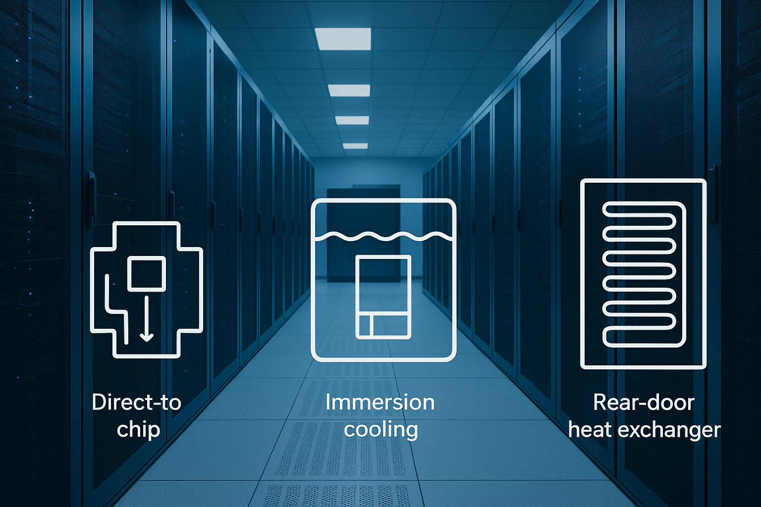
Is direct-to-chip liquid cooling the same as immersion cooling?
No. In D2C, coolant flows through cold plates attached to components. In immersion, the entire server (or major parts of it) sits in a bath of dielectric fluid. They solve similar density problems but have different service, compatibility, and facility implications.
Do I still need air cooling in a cold-plate system?
Often, yes. Cold plates target the hottest components, but some residual heat remains in the server and rack. Many deployments are hybrid (liquid for chips, air for the rest).
What’s the one KPI I should ask for if a vendor only shows me one chart?
Ask for inlet temperature stability under load ramps, plus the paired ΔT with flow at the same operating point. Those together tell you far more than a single steady-state number.
Next steps
If you’re scoping a pilot, the next most useful artifact is a one-page “loop requirements sheet” (inlet temperature range, minimum flow per branch, max ΔP, water quality assumptions, and commissioning tests).
If that would help, start with Coolnetpower’s cold plate liquid cooling solutions page, then request a commissioning checklist and a basic requirements template you can tailor to your rack densities and facility loop.