Table of Contents
ToggleIntroduction
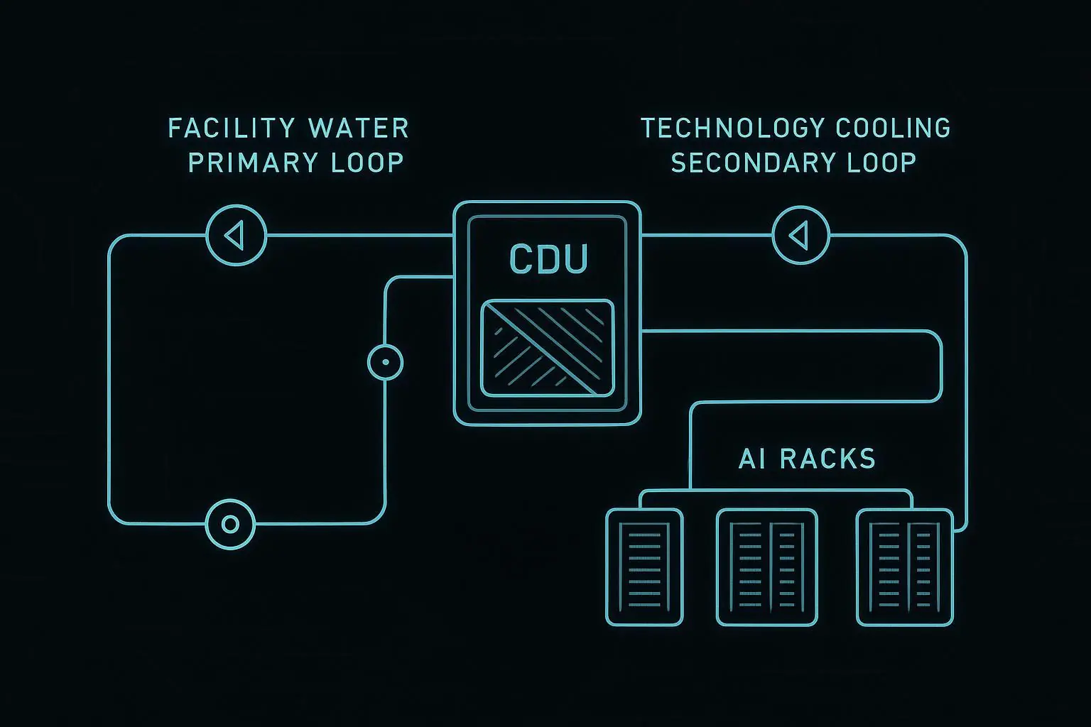
Sizing a coolant distribution unit (CDU) is not just picking a kW number from a datasheet. You’re sizing a boundary between facility water and the technology cooling system (TCS) feeding cold plates: flow, differential pressure, temperatures, controls, and the fault domain you’re willing to accept.
For AI racks, that boundary matters because loss-of-flow and loss-of-approach can turn into throttling—or a fast trip—long before a typical air-cooling alarm window closes.
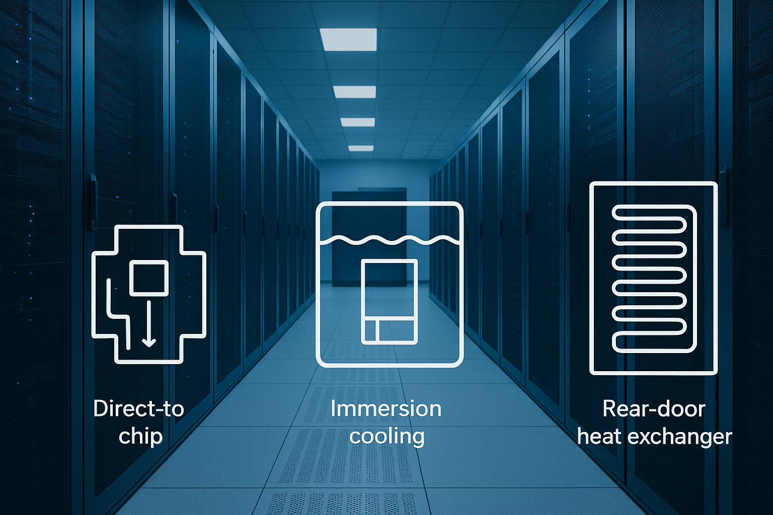
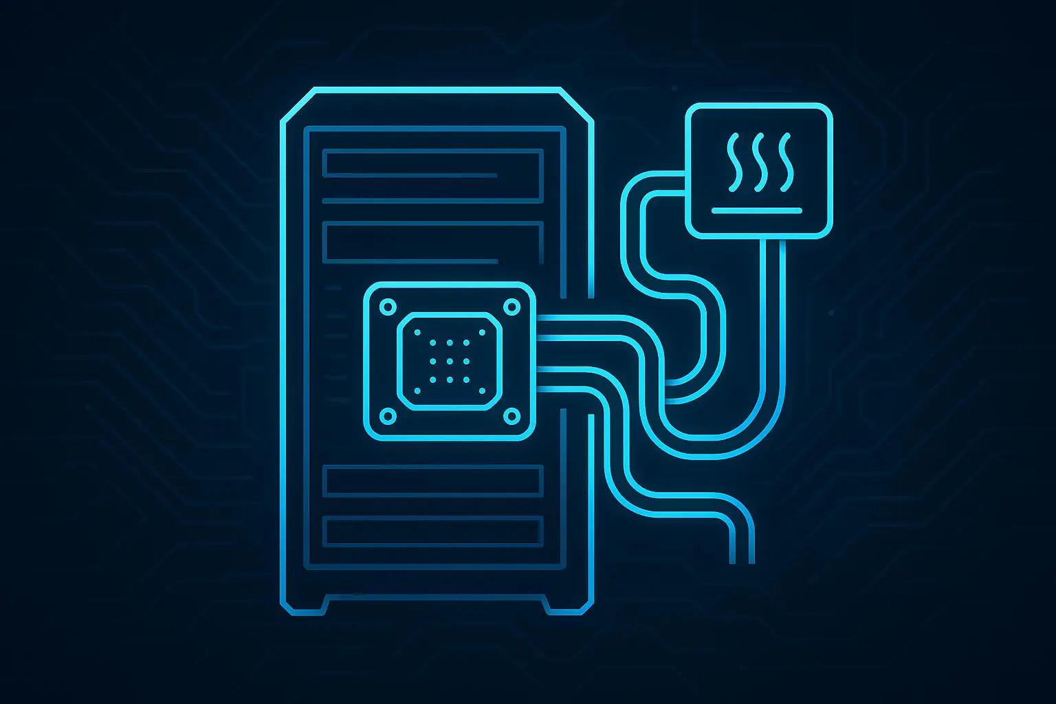
In direct-to-chip architectures, the CDU sits between the facility water system (FWS) and the TCS, typically using a liquid-to-liquid heat exchanger plus pumps, filtration, and controls. If you need a refresher on how the loops are separated and instrumented, see this direct-to-chip liquid cooling guide.
This guide is intentionally calculation-driven. We’ll start with the heat load and use the basic energy balance Q = ṁ·cp·ΔT (plus vendor limits and pump curves) to arrive at a CDU specification you can defend in an RFP and verify during commissioning.
Key Takeaway: A CDU that “meets kW” on paper can still fail in the field if flow, head, approach temperature, filtration loading, or control fault domains weren’t sized explicitly.
Define design inputs (CDU sizing inputs)
Establish heat load basis
Start by writing down the heat removal target you’re contractually sizing to—then identify what portion is actually on the liquid loop.
For this post, we’ll use per rack (kW/rack) as the basis, because it maps cleanly to:
rack manifold flow allocation,
cold-plate supplier flow limits,
the failure domain you’ll typically enforce with branch valves and leak zoning.
Practical checklist for heat-load basis:
Nameplate vs measured: If you have measured power, use it; otherwise use IT nameplate with a documented diversity factor.
Liquid-cooled fraction: In hybrid designs, define what share of rack power is on cold plates vs residual air.
Design point: Use the worst credible steady state for sizing (not the average training job).
Worked example baseline (we’ll use this later): 30 kW per rack.
Select target ΔT and coolant
Your two levers that most directly control required flow are:
allowable coolant temperature rise across the rack (ΔT), and
coolant properties (cp and density).
For water-based loops, cp is commonly taken around 4.186 kJ/kg·K for engineering calculations (see examples that state the relationship and constants in a cooling capacity calculator or Boyd’s note on the heat transfer equation Q = m·cp·ΔT). Glycol mixes reduce cp and change viscosity, which can increase flow requirement and pressure drop.
How to choose ΔT (pragmatically):
A larger ΔT reduces flow (smaller pumps, smaller piping), but pushes higher return temps and can tighten approach temperature constraints.
A smaller ΔT increases flow and pump power, but gives more temperature headroom at the cold plate.
For a first pass, pick a ΔT that your cold plate and rack distribution can tolerate, then verify it against vendor min/max flow and temperature limits.
Align S/W classes and dew point
Two temperatures have to “fit” at the same time:
The technology-side supply you need at the cold plates.
The facility-side supply you can realistically provide (and how “warm” you want it for chiller-lite operation).
This is where approach temperature and condensation risk show up.
Dew point: If technology-side supply drops below local dew point (or below the surface temperature of piping/manifolds), condensation becomes an operational risk. Vertiv’s CDU deployment notes explicitly call out keeping the secondary supply above dew point as a practical requirement in liquid-cooled deployments (see Vertiv’s CDU deployment best-practice notes, linked later in this guide).
ASHRAE-style W/S classes: Facility water “W-class” and technology supply “S-class” are a useful shorthand, but your commissioning team still needs numbers: supply setpoint, allowable excursions, and alarm thresholds.
Before you calculate flow, document:
required tech-side supply and return temperature bands,
facility water supply/return bands,
maximum allowed approach temperature across the CDU heat exchanger (and whether it’s fixed or flow-dependent).
Calculate rack/pod flow
Use Q = m·cp·ΔT for flow
At steady state, the rack’s liquid loop must carry away the heat load:
Q = heat removed (kW)
ṁ = mass flow (kg/s)
cp = specific heat (kJ/kg·K)
ΔT = coolant temperature rise across the rack (K or °C)
Rearrange:
ṁ = Q / (cp·ΔT)
For water, you can convert mass flow to volumetric flow using density ≈ 1 kg/L for a planning estimate.
Worked example (30 kW per rack)
Assumptions (explicit):
Coolant: water (planning cp ≈ 4.186 kJ/kg·K)
Target ΔT across rack: 5°C (you will validate this against cold-plate limits)
Calculation:
ṁ = 30 kW / (4.186 kJ/kg·K × 5 K) ≈ 1.43 kg/s
Volumetric flow ≈ 1.43 L/s ≈ 86 L/min
If you instead choose ΔT = 10°C, required flow roughly halves.
A useful sanity check is to compare your result with early planning rules-of-thumb. Vertiv notes a typical planning flow rate around ~1.5 L/min per kW, but also stresses it varies and must be validated against IT supplier limits (Vertiv best practices for installing and managing CDUs). For 30 kW/rack, that rule-of-thumb yields ~45 L/min—close to what you’d see with a larger ΔT than 5°C.
Convert L/min ↔ GPM
You’ll often need to communicate in both metric and US customary units.
1 US GPM ≈ 3.785 L/min
1 L/min ≈ 0.264 US GPM
Using the worked example:
86 L/min ≈ 22.7 GPM
If your RFP uses BTU/h, the common hydronic shorthand is:
BTU/h = 500 × GPM × ΔT°F
(That shorthand is widely used for water; if you use glycol or a non-water coolant, the constant changes.)
Validate with cold-plate limits
This is where many “paper sizes” fail.
Validate the calculated rack flow against:
Cold-plate and server vendor min/max flow (too low can reduce heat transfer; too high can exceed allowable ΔP or create control instability).
Quick-disconnect (QD) and manifold pressure ratings.
Acceptable rack ΔP at design flow (your pump head step will quantify this).
Operationally, treat vendor limits as hard constraints. If your calculated flow violates them, do not “average it out” across racks—adjust ΔT targets, branch balancing, or rack grouping.
Size pump head and hydraulics
Sum component pressure drops
Once flow is known, compute worst-case pressure drop around the controlling loop. The CDU pump must overcome the sum of:
cold plates,
rack manifold and balancing valves,
QDs and hoses,
headers, fittings, and isolation valves,
filters/strainers (at clean and end-of-life ΔP),
CDU heat exchanger and internal piping.
Procurement note: ask vendors for ΔP curves (ΔP vs flow) for each component or at least at key operating points.
Check pump curve operating point
Convert pressure drop to equivalent head and plot your duty point on the pump curve.
The conversion is:
H = ΔP / (ρg)
A pump vendor explanation of why head and pressure are related this way (and why density matters) is summarized in North Ridge Pumps’ note on head vs pressure.
What to verify on the curve:
At design flow, the operating point is not at the extreme right edge (low margin) or far left (unstable/recirculation risk).
There is margin for filter loading and minor future additions.
If you have variable-speed drives (typical), confirm stable control at minimum flow.
Control erosion-safe velocities
Velocity drives both pressure drop and erosion/noise risk. The right answer depends on materials, glycol %, and how many QDs/hoses you have, but the decision process is consistent:
Start from your required rack flow.
Choose hose/pipe IDs that keep velocities reasonable.
Recalculate pressure drop and iterate.
⚠️ Warning: “Undersized for neat routing” is a classic failure mode—small hoses and manifolds can create a pressure-drop cliff that forces pump upsizing and makes balancing unstable.
Map temperatures and approach
Set tech-side supply/return
Define a technology-side supply setpoint that:
meets cold-plate inlet requirements,
stays above dew point for your worst-case room conditions (or has a documented condensation control strategy),
allows stable control during load swings.
Then verify the implied return temperature at design ΔT.
Example (conceptual):
If tech-side supply is 35°C and rack ΔT is 5°C, return is ~40°C.
Coordinate facility W-class
Now check whether the facility side can support the technology side once you include approach temperature.
If your facility water supply is too warm (or too variable), you may be forced into:
a larger approach (warmer tech supply),
a larger heat exchanger and/or higher flow,
or a different heat rejection strategy.
Manage approach temperature
Approach temperature is the “pinch” across the CDU heat exchanger. The smaller you require it to be, the more heat exchanger performance you’re buying (and the more carefully you must validate fouling and flow distribution).
Commissioning implication: you must define how approach will be measured (sensor locations) and what happens when approach degrades (alarm thresholds, filter maintenance, flow adjustment).
Select capacity and redundancy
Choose CDU kW and flow range
Translate the rack result into a CDU capacity that covers:
kW capacity (heat exchanger + facility side capability), and
flow range (pump and control range),
at your required temperature approach.
Even if you’re sizing “per rack,” most CDUs serve a row or pod. Multiply rack flow by rack count, then add explicit margin for:
balancing and distribution losses,
filter end-of-life ΔP,
and realistic growth (if that’s in scope).
N, N+1, 2N architectures
Redundancy should be defined by what failure you can tolerate without violating thermal limits.
N: exactly enough CDU capacity for design load.
N+1: one extra unit (or pump/train) beyond what’s required so you can tolerate a single failure or do maintenance without dropping below required capacity.
2N: two fully independent paths, each capable of carrying full load.
Vertiv’s deployment guidance frames redundancy as a key driver of CDU placement and cost/space tradeoffs.
For AI liquid cooling, redundancy isn’t just “extra pumps.” Map the fault domain:
pump(s),
controls and power feeds,
valves and sensors,
heat exchanger path,
leak zone isolation.
If you want a deeper vendor-neutral discussion of how redundancy and monitoring map to fault domains, this background post on CDU sizing & redundancy for AI loads is a useful companion.
Placement: rack, row, pod
Placement is where engineering and delivery model meet.
Rack-level can simplify ownership (one rack, one loop), but increases unit count and distributed maintenance.
Row-level is a common compromise for space and service access.
Pod-level / centralized can improve redundancy efficiency (fewer units for N+1) but increases the size of the fault domain and raises the bar on distribution design and commissioning.
For compliance-sensitive, fast-expansion programs, the practical question is often: How quickly can you commission, prove alarms/interlocks, and replicate the design across pods without re-learning the same integration lessons?
This is where integrated modular delivery can matter. If your expansion model includes modular or micro data center blocks, aligning CDU placement with the module boundary can reduce rework in controls and commissioning: the CDU, its sensors, and its alarm logic become a repeatable “tested unit” rather than a bespoke integration each time. In Coolnetpower’s broader integrated solutions framing, the CDU sits alongside power and monitoring as part of an end-to-end package that’s commissioned as a system, not as disconnected components (see the Coolnetpower CDU overview for general context).
The key is to keep that advantage technical: clearer boundaries, repeatable test procedures, and fewer integration surprises—not marketing claims.
Specify fluid, filtration, monitoring
Water quality and inhibitors
Treat fluid chemistry as a reliability topic, not an afterthought.
Specify:
base fluid (water vs glycol mix),
material compatibility constraints,
inhibitor package requirements,
allowable conductivity/pH bands,
fill and makeup water process.
If you’re integrating with multiple vendors (cold plates, manifolds, CDU), require a single consolidated compatibility statement during submittals.
Filtration and DP monitoring
Filtration protects cold plates and valves from particulate fouling.
Operationally important details to specify:
filter micron rating and placement,
clean and end-of-life differential pressure (ΔP) targets,
whether filter change can be done without shutting down the entire served domain.
Vertiv notes CDUs commonly include supply-side filters (example given: 50-micron) as part of practical deployment considerations. Even if you choose a different filtration scheme, the principle stands: specify filtration with monitoring so maintenance is proactive rather than reactive.
Leak detection and telemetry
Your sizing effort is incomplete until it’s monitorable.
Minimum telemetry points most commissioning teams will want to trend:
tech-side supply/return temperatures
tech-side supply/return pressures and ΔP
loop flow rate
pump status/speed (duty + standby)
filter ΔP
leak detection status by zone
Pair telemetry with alarm tiers and interlocks that match your fault domain:
warning alarms for drift (approach degradation, filter ΔP rising),
urgent alarms for low flow/high temperature,
automatic actions that are tested (not assumed) during commissioning.
Conclusion
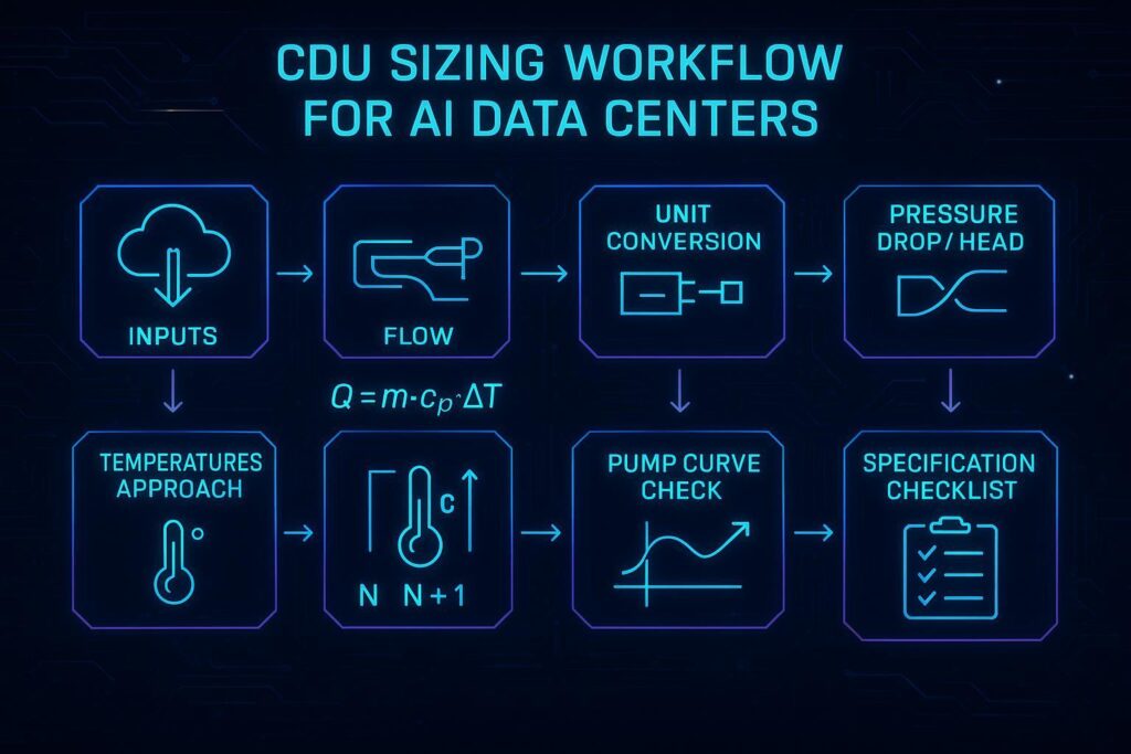
A defensible CDU selection is the result of a sequence—not a single kW number.
Define the inputs (heat load basis, ΔT/coolant, dew point and temperature classes).
Calculate flow from Q = ṁ·cp·ΔT, then validate against cold-plate and rack distribution limits.
Size pump head by summing pressure drops and verifying the operating point on the pump curve.
Map tech-side and facility-side temperatures and confirm approach temperature is achievable and monitorable.
Choose capacity and redundancy (N, N+1, 2N) based on fault domain and maintenance strategy.
Specify chemistry, filtration, leak detection, and telemetry so the system is controllable and auditable.
Final checklist (copy/paste into your RFP):
Inputs: kW/rack basis, liquid-cooled fraction, design ΔT, coolant properties, dew point policy
Flow: required L/min and GPM per rack + min/max vendor limits
Head: full loop ΔP budget + conversion to head + pump curve duty point
Temperatures: tech supply/return targets, facility supply/return bands, max approach
Redundancy: N vs N+1 vs 2N stated as fault domains (pumps, HX, power, controls)
Chemistry: water quality bands, inhibitors, compatibility sign-offs
Monitoring: temp/pressure/ΔP/flow, filter ΔP, leak zoning, alarm tiers and tested interlocks
If you want, we can turn that checklist into a one-page commissioning worksheet (inputs → expected readings → acceptance criteria) for your specific rack count and facility water temperatures.