If you’re planning (or already operating) high-density AI infrastructure, you’ll eventually run into the same question: what are the real air cooling limits for high-density AI racks—and how do you know you’ve crossed them?
This article defines what “air cooling fails” actually means in operational terms, using OEM-style GPU power data, inlet-temperature guidance, DCIM heatmaps, and what throttling looks like under sustained AI load.
Table of Contents
ToggleDefinition: what it means when “air cooling fails”
In high-density AI racks, air cooling fails when the facility can no longer deliver enough cool air to the servers’ inlets (uniformly, continuously, and efficiently) to keep GPUs and CPUs within their safe operating envelopes without triggering a cascade of penalties—typically fan saturation, recirculation-driven hot spots, and eventually GPU thermal throttling.
This is not the same as “the data hall is warm.” The failure mode is usually local: a few racks, a few U-spaces, or the top-of-rack inlets drift outside target conditions while the room-average numbers still look fine.
Key Takeaway: In AI rooms, “air cooling fails” is less about making cold air and more about delivering it to the inlets without mixing, pressure loss, and runaway fan power.
Why this problem shows up now
AI servers changed the thermal math.
A single data-center GPU used to be a few hundred watts. Today’s platforms are commonly discussed in the ~700 W class (for example, NVIDIA H100 SXM modules are widely cited at 700 W) and the next generation includes ~1,000 W-class accelerators (see Lenovo’s OEM-style spec sheet for a ThinkSystem NVIDIA HGX B200 180GB 1000W GPU).
When you stack eight of these accelerators into one chassis (plus CPUs, memory, NICs, and PSU losses), you’re no longer designing around “a server room problem.” You’re designing around continuous, concentrated heat.
At the facility level, ASHRAE’s thermal guidance reinforces that the controlling variable is what the IT actually sees at the intake—not the room average. In ASHRAE TC 9.9 terms, the commonly cited recommended inlet range for air-cooled IT is 18–27°C, while high-density guidance introduces tighter envelopes (for example, H1 is often summarized as 18–22°C recommended). ASHRAE also emphasizes these limits apply to the ITE inlet conditions (not general “space” conditions); see ASHRAE’s Thermal Guidelines reference card (5th edition) and ASHRAE’s discussion of the high-density transition in Emergence and Expansion of Liquid Cooling in Mainstream Data Centers.
The trendline is straightforward: higher chip power density means less margin for uneven inlet conditions—so the air cooling limits for high-density AI racks show up earlier than most legacy design rules assume.
The thermal limits that make air cooling break down
Air cooling hits its practical limits through a few linked mechanisms.
1) You can’t cheat airflow physics
To remove more heat with air, you need either colder supply air, more airflow, or both. In high-density racks, “more airflow” often runs into real constraints: restrictive chassis designs, cable congestion, imperfect blanking, raised-floor limitations, and pressure losses across the distribution path.
When resistance increases, fans must push harder. And fan energy doesn’t scale gently.
The fan affinity laws (often taught as “the cube law”) describe why: for similar fans, airflow roughly scales with speed, pressure scales with the square of speed, and power scales with the cube of speed. A clear explanation is in Axair’s Understanding basic fan laws.
Operationally, that means a modest push for “a bit more airflow” can become a large jump in fan power—often inside the servers themselves.
2) Recirculation and bypass create local hot spots
Most air-cooled failures aren’t “the whole room is too warm.” They’re “this rack is ingesting its own exhaust.”
Recirculation tends to appear when:
cold/hot aisle separation is imperfect
blanking panels are missing
cable cutouts leak
floor tiles or overhead supply are mis-aimed
top-of-rack areas starve for cold air while lower U-space looks fine
DOE guidance on air management focuses heavily on controlling conditions at the IT equipment intake and reducing bypass/recirculation; see the U.S. Department of Energy’s Best Practices Guide for Energy-Efficient Data Center Design (2024).
3) Inlet temperature, not room average, becomes the governing constraint
At higher densities, you can maintain an acceptable average aisle temperature and still have inlets at the top of racks drifting upward due to stratification and mixing.
This is why inlet measurement is emphasized in ASHRAE’s guidance and in operational best practices: if you only watch room sensors, you can miss the temperature the servers actually ingest.
Air cooling limits for high-density AI racks in practice
A useful way to think about air cooling limits for high-density AI racks is not as a single “kW per rack” ceiling, but as a point where maintaining stable inlet conditions becomes disproportionately costly and fragile.
In practice, you’re usually at (or past) that point when:
a subset of racks repeatedly runs hot even after setpoint reductions
fans are routinely near their upper control range
you see persistent inlet non-uniformity (top vs mid vs bottom)
you see recurring GPU thermal throttling during sustained training runs
If you’re planning density increases, it helps to treat GPU rack density as a roadmap variable: what’s survivable for mixed CPU racks may not be survivable for accelerator-heavy racks with sustained utilization.
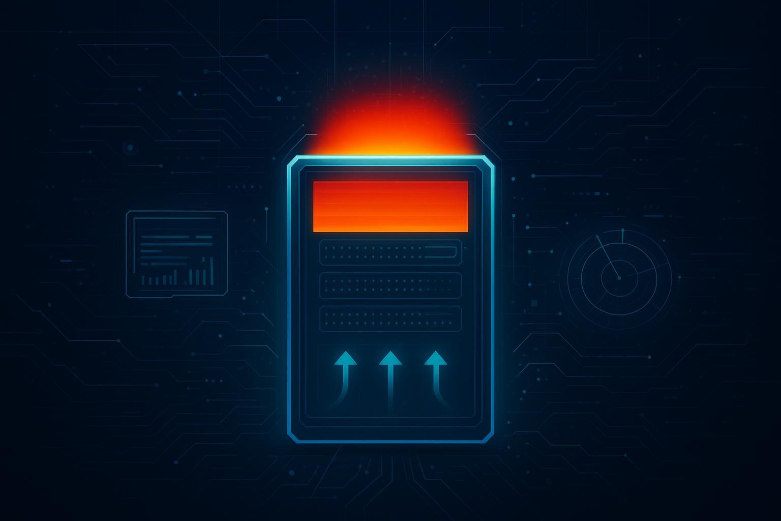
What “failure” looks like in operations (a diagnostic definition)
If you want a field-usable definition, air cooling is “failing” when one or more of the following becomes persistent under sustained AI load:
Symptom | What you’ll see | Why it matters |
|---|---|---|
Inlet non-uniformity | heatmap shows hot stripes/top-of-rack hot spots; large gradient front-to-front across racks | local hot spots drive throttling risk even when averages look OK |
Fan saturation / runaway | server fan RPM near max; fan power climbs; acoustics worsen | fan power tax rises and still may not fix inlet conditions |
Alarms you can’t tune away | repeated thermal warnings at specific racks/U spaces | indicates airflow path or containment failure, not “bad setpoints” |
Throttling events | GPU clocks/power-limit reductions under load | reduces effective compute and can lengthen training jobs |
On AI training specifically, throttling can become a system-wide penalty. Distributed training efficiency can be sensitive to hardware/environment variability, and throttling behavior can vary across physical environments in ways that impact throughput; see ACM’s study Characterizing the Efficiency of Distributed Training: A Power … (2025).
How to use DCIM heatmaps to prove (or disprove) the problem
The best time to act is when you have evidence—not when someone says “the GPUs feel hot.”
A practical rack-monitoring approach is:
Measure rack inlet temperature at multiple heights (top / middle / bottom) on representative racks.
In higher-density zones, add matching rear exhaust sensors so you can distinguish “not enough cold air” from “mixing/recirculation.”
Vertiv summarizes a rack-level approach that uses multiple sensors per rack in its guidance on rack temperature monitoring. For how DCIM turns sensor data into actionable visibility (hot spots, capacity planning, and containment validation), Modius gives a practical overview in its note on how DCIM helps optimize containment.
What to look for in the heatmap:
persistent top-of-rack inlets hotter than mid/bottom
end-of-row anomalies (boundary effects)
hot racks next to “cold” racks (a mixing/air path issue, not a room setpoint issue)
heat that correlates with workload (sustained training runs) rather than random spikes
What air cooling can still do well
Air cooling is not obsolete. It’s excellent when the airflow path is short, sealed, and predictable—and when rack density and chip heat flux stay within a range where you can maintain stable inlet conditions without excessive fan energy.
If you’re still planning your density roadmap, it can help to treat rack power as bands rather than a single “limit.” For a practical sizing workflow (including density bands, redundancy considerations, and the instrumentation that makes heatmaps meaningful), see Coolnetpower’s guide on Sizing power and cooling for high-density AI racks (30–80 kW).
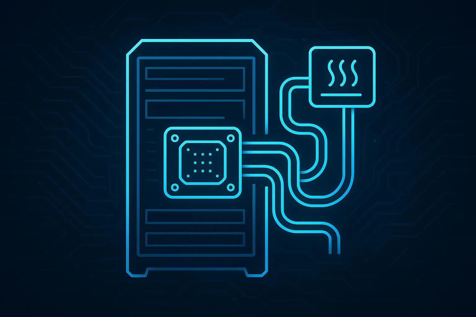
What comes after air cooling (directional, not a sales pitch)
Once you’re consistently fighting inlet non-uniformity and fan power, you typically have three paths:
Optimize airflow management (containment, sealing, tile placement, cable discipline, setpoint governance).
Use air-assisted approaches like rear-door heat exchangers as a bridge in some retrofit scenarios.
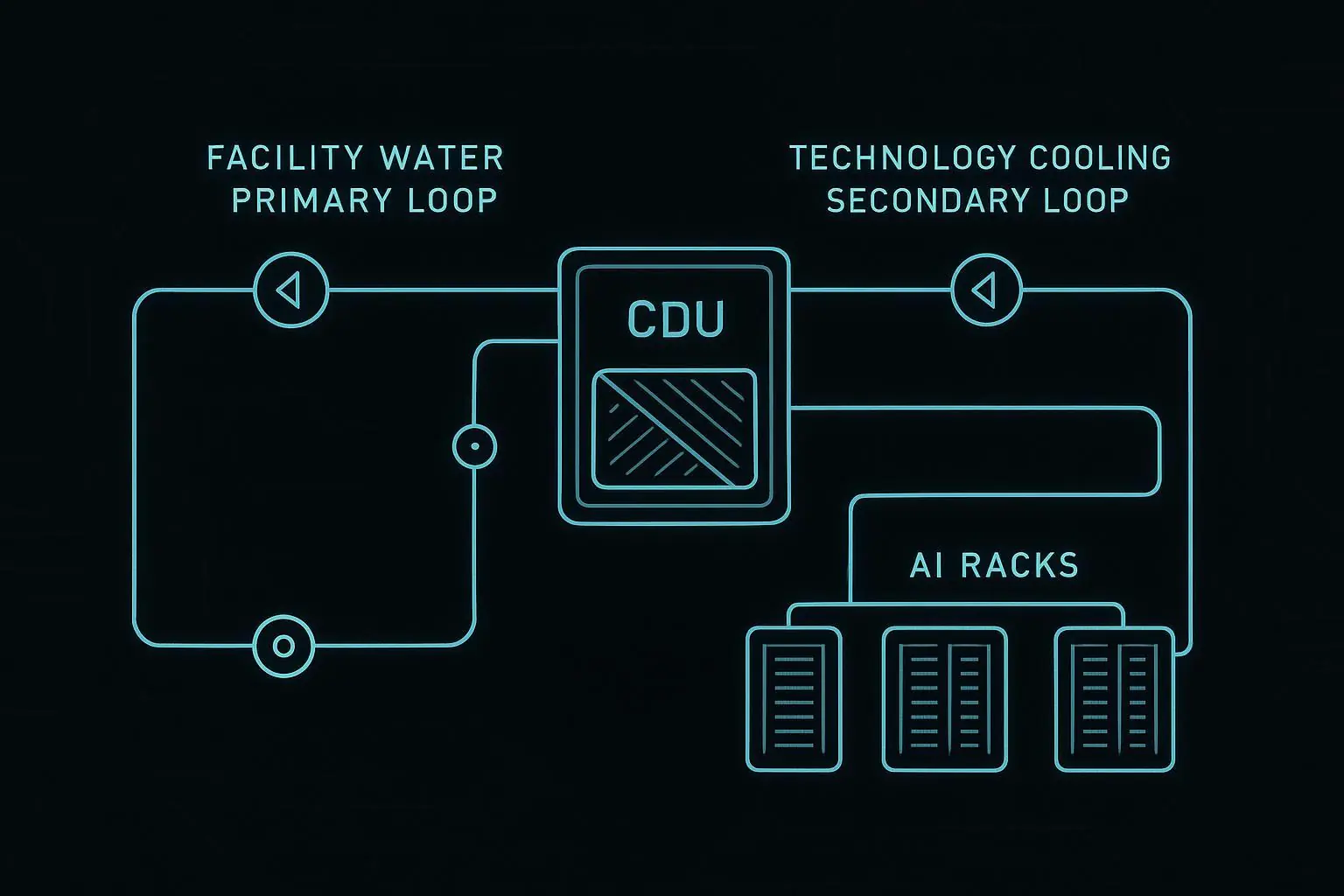
Evaluate direct-to-chip liquid cooling for sustained high-density accelerator loads.
If you want a balanced framing of common misconceptions and what liquid cooling does (and does not) solve, Coolnetpower’s article on The Biggest Misconceptions About Liquid Cooling in Data Centers is a useful starting point.
For a broader roadmap view that ties “optimized air → hybrid → liquid” into facility planning, see Hybrid paths to scale AI cooling and the deeper background in The Ultimate Guide to AI Data Center Cooling.
Sidebar: a qualitative Coolnetpower field note
Coolnetpower teams typically see the same pattern in high-density AI rooms: the first operational bottleneck is rarely total cooling capacity on paper—it’s inlet consistency.
If the monitoring is sparse (few inlet sensors, no per-rack visibility), operators tend to “solve” symptoms with lower setpoints and higher airflow, which can increase fan energy and still leave a subset of racks throttling.
A more durable workflow is to instrument the problem (rack inlets at multiple heights, then heatmaps), confirm the failure mode, and then choose the least disruptive cooling step that restores inlet stability.
FAQ
Do next-gen AI servers exceed what air cooling can handle?
They can—especially when accelerator power and rack density push you into a regime where maintaining uniform inlet temperatures requires excessive airflow and fan power, or where mixing/recirculation triggers hot spots. The failure condition is usually visible in rack inlet heatmaps before it becomes a headline problem.
What rack densities typically stress or break air cooling limits?
There isn’t one universal number, but many engineering and industry discussions treat ~20–30 kW per rack as the range where conventional air approaches become increasingly difficult, and where hybrid or liquid-assisted strategies become more common. Treat this as a planning band, then validate with your own inlet temperature uniformity and throttling telemetry.
Which GPUs force liquid adoption today?
It’s less about a single GPU model and more about the system configuration: multi-accelerator servers with ~700 W-class modules and emerging ~1,000 W-class parts compress a large, continuous heat load into a small volume. When that drives high rack densities and persistent inlet hot spots, liquid options become the durable path.
How does throttling impact AI training time?
Throttling reduces effective compute throughput by lowering clocks and/or enforcing lower power limits. In distributed training, a slowed worker can constrain overall job throughput because synchronization points make the job progress at the pace of the slowest participant.
Next steps
If you want a neutral, engineering-first way to assess risk before a retrofit or expansion, request a rack thermal readiness checklist (inlet sensor placement, heatmap thresholds, and a “throttling watch list” for your monitoring stack).