Introduction
Edge sites are being asked to do more with less: higher rack densities, tighter build timelines, and stricter efficiency reporting with fewer people on-site. The result is a familiar failure mode—cooling becomes the constraint long before power or floor space.
Rack-mounted cooling shifts the problem from “cool the room” to “control the rack.” By localizing capacity, it can shorten deployment cycles, contain thermal risk, and keep AI workloads stable as densities climb.
This article outlines practical density thresholds, rack/row architectures, and compliance-ready metering practices for decision-makers.
Precision at the rack
Localized thermal control
Rack-mounted cooling works because it moves heat capture closer to the source. That single architectural change often lets you operate with warmer water (or a smaller air-side delta) for the same silicon limits—one of the reasons liquid-based approaches can be materially more efficient than room-level air alone.
The U.S. Department of Energy’s LBNL Data Center Efficiency program makes the principle explicit: when you transfer heat close to the source, the cooling liquid supply can be warmer while still meeting requirements, improving plant-side efficiency and free-cooling potential (LBNL’s “Liquid Cooling” overview).
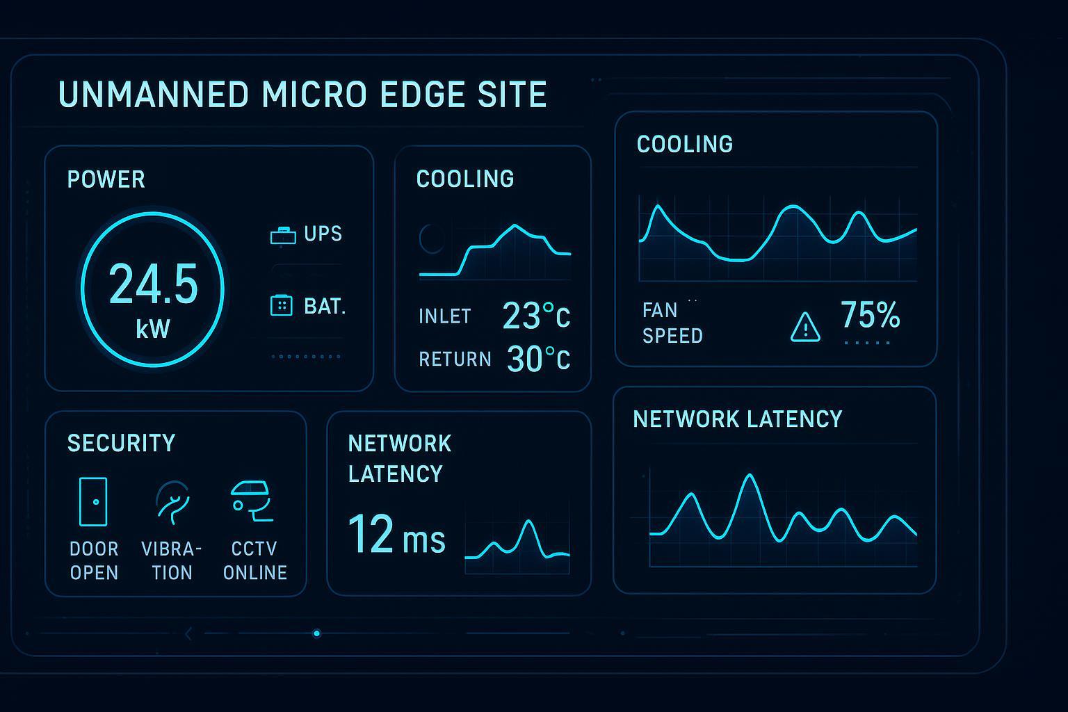
In edge terms, “localized control” means you can stabilize rack inlet conditions even when the room is imperfect: partial containment, mixed legacy loads, or uneven airflow paths. It’s also easier to tune for what operators actually care about—GPU throttling avoidance and inlet stability—rather than chasing room averages.
Failure domain and redundancy
Edge reliability is often less about theoretical MTBF and more about blast radius. Room-level cooling failures can impact an entire module. Rack-level cooling can be designed so a single component failure degrades a rack (or a small pod) instead of the full site.
Practically, you get more options for redundancy design:
Multiple smaller CDUs sharing load (N+1 at the pod level)
Isolation valves that let you service a branch without draining the entire loop
Instrumentation that alerts operators before a drift becomes an incident
This is one reason rack-mounted cooling is attractive for sites with limited on-site staff: you can make the system more observable and more serviceable without increasing the size of the “affected area” when something goes wrong.
Integration patterns in constrained sites
Edge sites rarely have the luxury of greenfield mechanical rooms. Common integration patterns include:
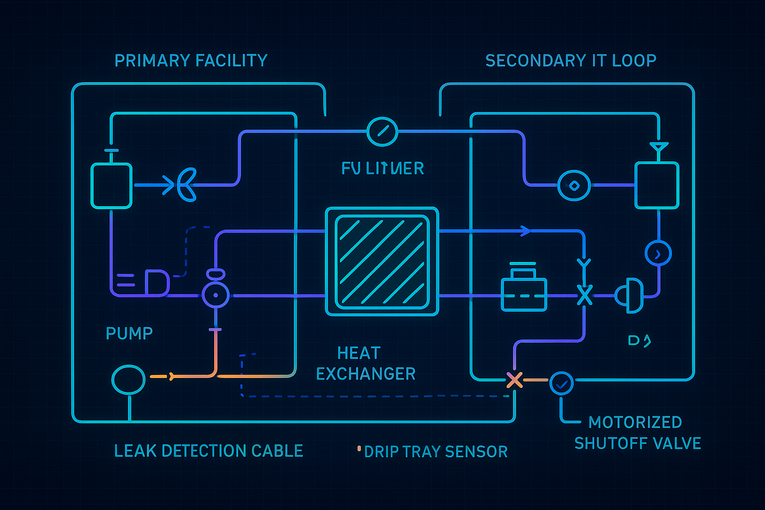
Rack-level secondary loop + facility loop: an in-rack CDU isolates IT coolant from the building loop.
Row manifolds with isolation: valved headers allow fast additions and maintenance windows without full shutdown.
Hybrid airflow + liquid capture: keep optimized air for the residual heat while shifting the highest heat flux to liquid.
A useful way to think about it is phasing:
optimize airflow and containment where it’s cheap and fast,
add rack-mounted cooling where density forces it,
standardize manifolds, metering, and alarms so you can replicate the pattern across micro-sites.
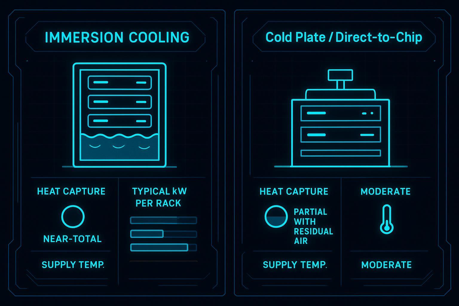
For teams building hybrid rows, Coolnetpower’s comparison of options can help frame where rear-door heat exchangers fit versus chip-level approaches (Direct-to-chip vs immersion vs rear-door heat exchanger compared).
Density and AI readiness
Air vs liquid thresholds
The decision point for rack-mounted cooling is usually not ideology—it’s density plus risk tolerance. In procurement terms, you’re looking for air vs liquid cooling thresholds that are defensible for your racks, climate, and uptime target.
Vertiv’s 2025 high-density cooling guide notes rear-door heat exchanger (RDHx) ranges that are helpful as a bridge: passive RDHx for roughly 5–25 kW, and active units around 50 kW nominal (tested above 70 kW) (Vertiv’s high-density cooling guide, 2025).
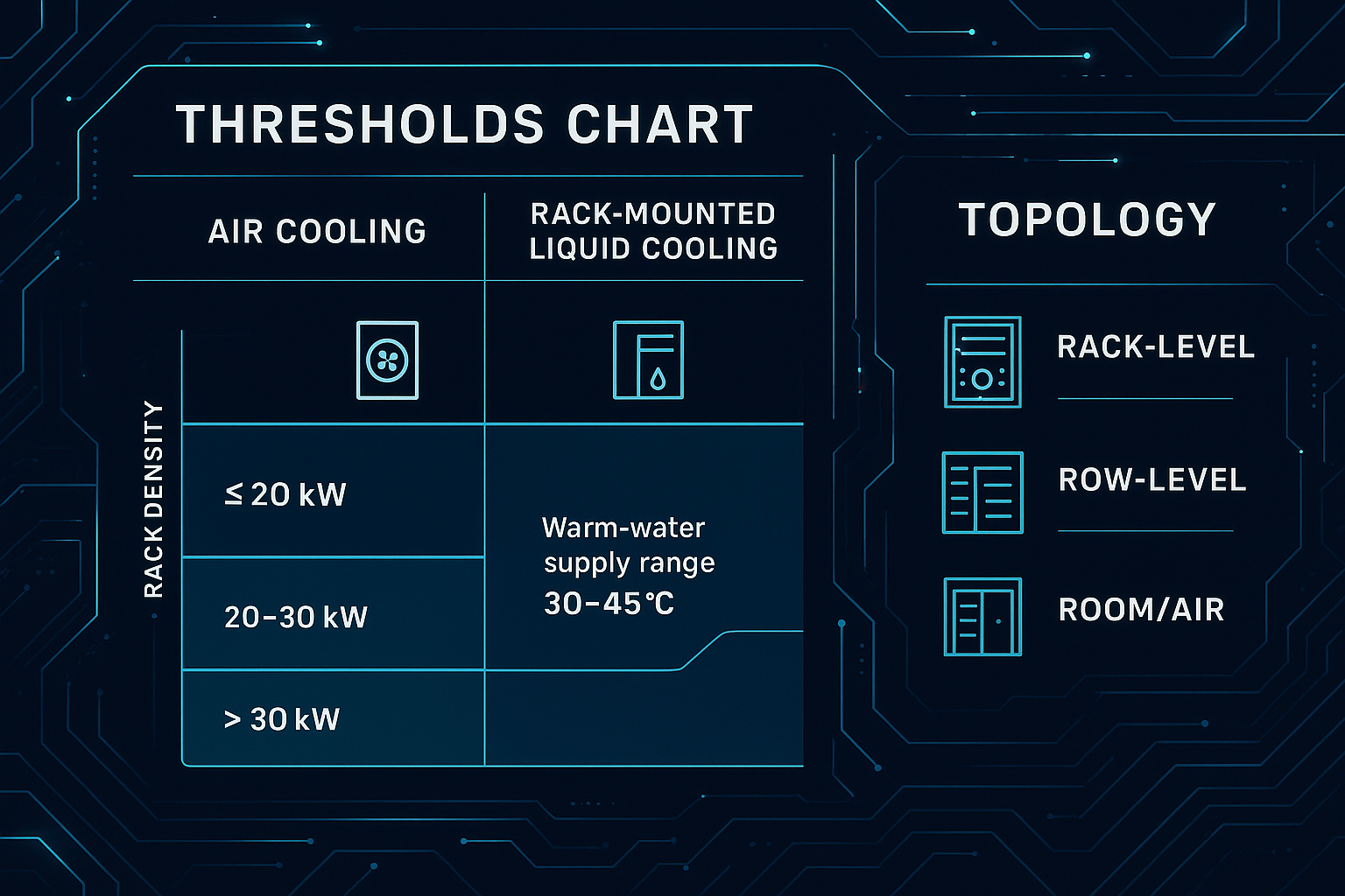
For rack-mounted cooling for edge data centers, the practical thresholds often show up like this:
Rack density band (sustained) | Typical edge-friendly approach | What usually breaks first |
|---|---|---|
≤ ~20 kW/rack | Optimized air + containment + rack-level airflow discipline | Air distribution (bypass/recirculation), fan energy, hot spots |
~20–30 kW/rack | Hybrid: optimized air plus rack-level heat capture (often RDHx or rack-mounted assist) | Hotspot control under transient AI loads; serviceability |
> ~30 kW/rack | Liquid becomes the primary path; rack/row CDUs and standardized manifolds | Facility interface (loops, redundancy), leak risk controls, monitoring |
One internal reference that’s useful when stakeholders ask “how far can we push the bridge?” is Coolnetpower’s RDHx capacity discussion for the 20–40 kW planning band (RDHx heat removal capacity for 20–40 kW racks).
Warm-water operations and dry coolers
Warm-water operation is one of the most underappreciated levers for edge sites because it changes both efficiency and siting constraints.
NVIDIA describes a 45°C liquid-cooling architecture for AI systems where hotter coolant enables more hours of dry-cooler heat rejection and can reduce cooling water consumption dramatically in favorable climates (NVIDIA’s 45°C liquid-cooling architecture, 2026). Regardless of whether you adopt the same temperature envelope, the direction is clear: warm-water liquid cooling—capturing heat at the rack/chip—makes higher water temperatures practical, which can reduce reliance on chillers and evaporative heat rejection.
For edge deployments, the operational implication is less “copy this exact design” and more “spec the interfaces for it”:
Define allowable supply/return temperature ranges early (and who owns them: IT vs facilities).
Treat water temperature as an availability parameter (dew point control, alarms, safe modes).
Validate heat rejection options by climate and noise constraints (dry coolers, hybrid coolers, or existing DX paths).
Roadmap for mixed environments
Most edge portfolios will be mixed for years: legacy air-cooled racks, moderate-density compute, and a smaller number of AI racks that spike.
A pragmatic roadmap is to standardize the interfaces so you can mix without chaos:
Standard manifold locations and isolation strategy (so adds don’t become custom projects)
A consistent sensor set (flow, supply/return temperature, pressure; plus leak detection)
Acceptance tests that are density-aware (validate inlet stability under steady state and a defined transient)
If you’re actively managing GPU throttling risk in moderate-density zones, this operational approach is worth adopting: treat rack-level cooling as a control system with telemetry → alarms → response, not as a passive mechanical add-on (Stop AI/HPC throttling with rear door heat exchangers).
Deployment and reliability
Prefab speed and retrofit ease
Rack-mounted cooling aligns with the way edge sites are actually deployed: repeatable blocks, minimal site work, and faster commissioning. It’s also retrofit-friendly because you can upgrade the thermal architecture in-place—row by row or rack by rack—without rebuilding the entire room.
In practice, this supports two procurement patterns:
Start with a validated “density band” reference architecture (20–30, 30–50, 50+ kW/rack)
Order repeatable kits (manifold + CDU + sensors + controls) rather than one-off designs
Leak mitigation and safety
Liquid at the rack is a solvable risk, but only if it’s engineered as a safety system—not just plumbing.
Three practices separate reliable deployments from fragile ones:
Detect fast: leak detection cable or trays placed where a real leak shows up first (quick connects, CDU base).
Isolate automatically: motorized shutoff valves that close on alarm, plus a defined pump response.
Prove the response: acceptance tests that demonstrate what happens during loss of flow, sensor failure, or leak alarm.
⚠️ Warning: If leak detection and isolation aren’t integrated into controls and commissioning, “liquid cooling risk” becomes an operations problem—usually discovered during the first real incident.
Tier III/IV topologies at rack/row
You don’t need to label an edge site “Tier III/IV” to borrow the reliability thinking: remove single points of failure, constrain failure domains, and make maintenance possible without downtime.
At rack/row level, that typically translates into requirements like:
N+1 CDU capacity at the pod level, with each unit carrying a bounded share of load
Dual isolation paths (valved branches so a failed component can be bypassed)
Redundant sensing where it matters (inlet temperature and flow are more actionable than return averages)
Defined degraded-mode behavior (what happens to AI racks on alarm: throttle policy, load shed, or failover)
This is the practical version of Tier III/IV rack redundancy thinking: maintenance and faults should not take down the whole edge module.
The key procurement point: ask vendors to show the service story—how you isolate, drain, refill, and return to service—and how those steps are reflected in commissioning and operator runbooks.
Efficiency and compliance
PUE/WUE impacts at rack domain
Rack-mounted cooling can improve energy performance when it enables warmer water, fewer fan watts, and more hours of economization—but only if you can measure boundaries cleanly.
At the rack domain, treat metering as part of the architecture:
Thermal metering: flow + supply/return temperatures at the CDU/branch
Electrical metering: CDU power, pumps, and any supplemental air-side equipment
Control logs: alarms, isolation events, setpoint history (audit trail)
Coolnetpower integrates metering and monitoring (power, temperature, flow, alarms) to support rack-level performance tracking and KPI-ready reporting—without hiding risk behind marketing language.
EN 50600 and EED KPIs
If you operate in Europe (or sell into Europe), EN 50600 is a practical reference point because it connects facility design, availability classes, and operational management to measurable outcomes.
A CEN-CENELEC overview of green data centre standardization highlights how EN 50600 includes requirements and recommendations for monitoring/metering infrastructures needed to calculate and present operational KPIs (CEN-CENELEC’s EN 50600 overview brochure).
Separately, EU energy-efficiency policy is making KPI reporting less optional. Danfoss summarizes the EU Energy Efficiency Directive (EED) requirement for data centers above a 500 kW threshold to report KPIs including PUE, WUE, Energy Reuse Factor (ERF), and Renewable Energy Factor (REF) (Danfoss on EU data center KPI reporting under the EED).
For edge portfolios, the takeaway is operational: if you standardize rack/row metering now, you avoid rebuilding measurement later to satisfy reporting, audits, or RFP evidence.
Heat reuse opportunities
Rack-level liquid loops make heat reuse more feasible because they can deliver higher-grade heat than air exhaust. Warm-water operation can also improve the economics of heat recovery (for example, feeding a heat pump loop) compared to low-temperature, high-volume air streams.
Even if a given edge site has no local heat sink today, designing the loop interfaces and metering for future reuse is a low-regret move—especially where reporting is evolving toward energy reuse factors.
Conclusion
Edge sites choose rack-mounted cooling when they need a repeatable path to higher densities without expanding the cooling failure domain. The practical work is in the thresholds and the architecture: decide where air still works, where hybrid makes sense, and where liquid becomes the primary path.
Key takeaways:
Use density bands to choose the architecture (air → hybrid → liquid), not brand preferences.
Treat rack-level cooling as a control and safety system (instrumentation, leak detection, isolation, acceptance tests).
Map your design and metering to compliance early (EN 50600-aligned KPIs and EED-style reporting).
Next steps: align RFP criteria with density targets, redundancy at rack/row, and KPI reporting requirements. If helpful, request a commissioning checklist and metering points list for your target rack density band.