Introduction
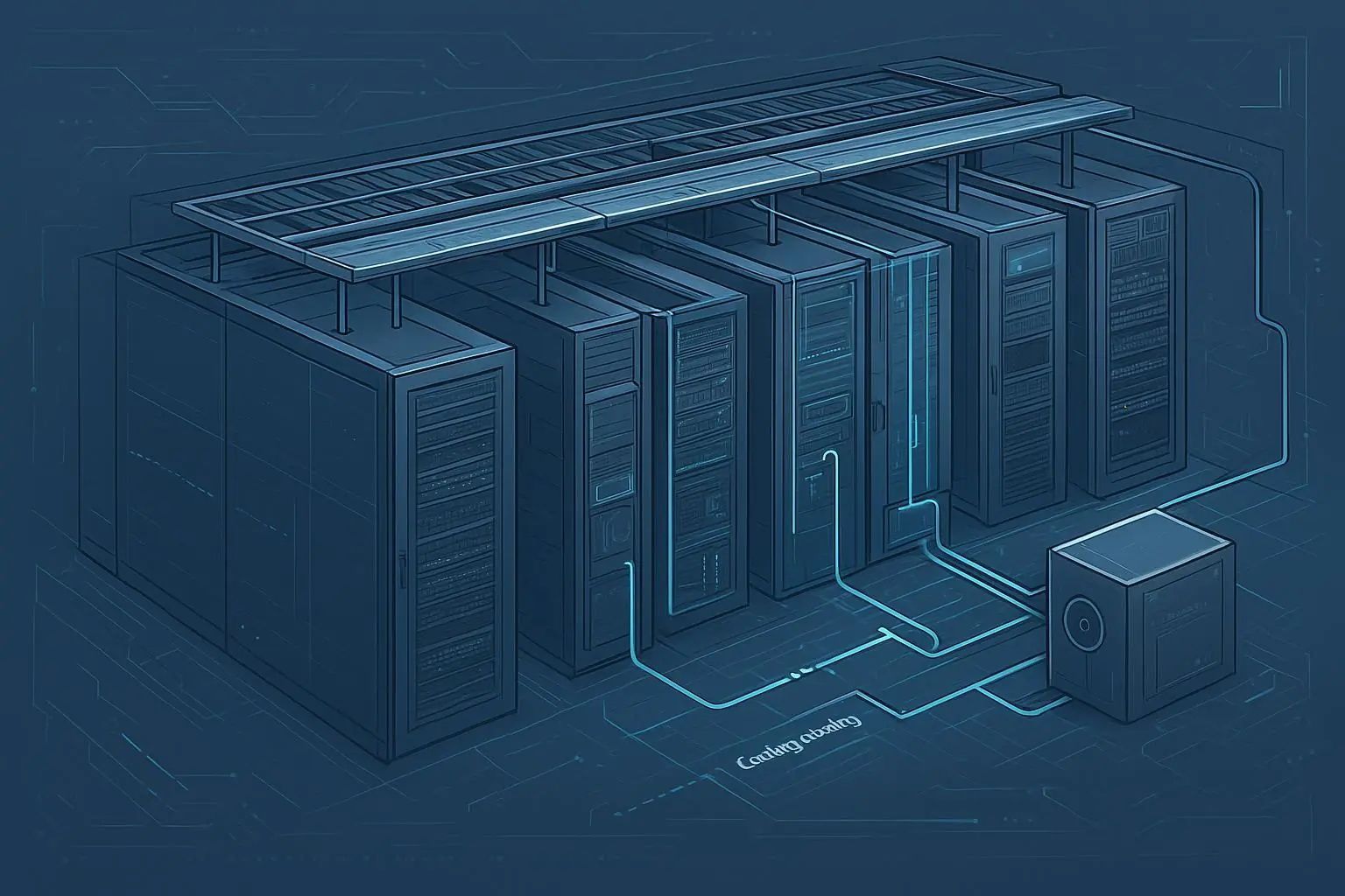
In-row cooling is a close-coupled approach: you place cooling capacity in the row, where the heat is generated, so airflow doesn’t have to travel across the room before it’s useful. In AI-ready rows—where rack loads can swing fast and hotspots can form in minutes—that distance and delay is often the difference between stable inlet conditions and throttling risk.
What in-row cooling solves in AI-ready rows:
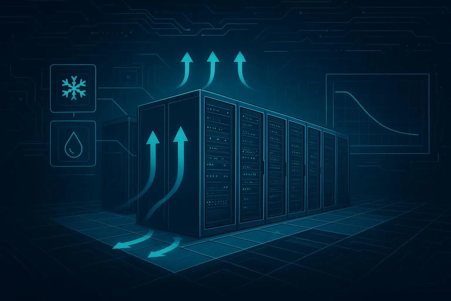
Hotspot control at the row level when a few racks outrun the room average
Predictable airflow delivery in mixed-density halls (legacy + GPU islands)
Faster commissioning because the “unit + row + controls” boundary is clearer than room-scale tuning
Containment compatibility (hot/cold aisle or full containment) to reduce bypass air and recirculation
This article is a selection guide anchored to:
ASHRAE TC 9.9 environmental envelopes (what “acceptable” looks like at the IT inlet)
ASHRAE 90.4 efficiency framing (what mechanical/electrical losses you’ll be judged on)
EN 50600 alignment and EU EED reporting expectations (what you’ll need to meter and disclose)
When in-row cooling fits (and when it doesn’t):
Best fit: rows that are trending upward in kW/rack, where you need controllable airflow and clear failure domains, but you’re not ready (or not uniform enough) for full direct-to-chip liquid.
Consider rear-door heat exchangers (RDHx) when the limiting factor becomes exhaust heat removal and room airflow starts to look like an expensive way to move sensible heat.
Consider direct-to-chip (D2C) liquid when the liquid-cooled fraction is high and air becomes a “residual” path—useful for electronics and comfort, not for primary heat transport.
Hotspot risk, failure domains, and time-to-commission are the real decision drivers in AI halls:
Hotspots rarely announce themselves at the room sensor. They show up at the IT inlet.
Failure domains need to be explicit: if an in-row unit trips, how many racks drift out of envelope—and how fast?
Time-to-commission matters because AI programs don’t wait for seasonal tuning; you need a topology that can be validated quickly with repeatable tests.
How to use this guide:
Start with the standards envelope so your “targets” are defensible.
Use density bands and pivot points to shortlist topologies.
Design containment, sensing, and controls as one system.
If hybrid liquid is in scope, design the hydraulic boundary early.
Commission against measurable acceptance criteria (air + liquid + metering).
Standards Alignment
ASHRAE TC 9.9 envelopes
ASHRAE TC 9.9’s core practical message is simple: design and operate to conditions at the IT equipment inlet, not “room average.” The most useful way to apply it in an AI-ready row is to treat the recommended/allowable envelopes as a contract boundary for your controls and alarms.
Two implications that matter for in-row designs:
Tight inlet control is often required for high-density equipment. ASHRAE’s 2021 update introduced a distinct high-density class and highlighted that these systems can require narrower temperature bands than general-purpose servers, which makes close-coupled delivery and containment more relevant. See the ASHRAE TC 9.9 Thermal Guidelines reference card and Uptime Institute’s summary of the change in “New ASHRAE guidelines challenge efficiency drive” (2021).
Humidity control is no longer “just RH.” The same TC 9.9 update emphasizes dew point and pollutant/corrosion considerations. Even if your in-row units are not doing humidification, your row design needs to assume humidity swings and prove you avoid condensation at cold surfaces.
Practical rule: write your acceptance criteria as “inlet temperature and moisture at the rack face stays inside the chosen envelope during normal operation, and stays inside allowable during defined fault scenarios.”
ASHRAE 90.4 efficiency levers
ASHRAE 90.4 doesn’t reward good intentions—it rewards measured, modeled, and managed losses. For cooling selection, the key is that 90.4 evaluates mechanical and electrical efficiency using the Mechanical Load Component (MLC) and Electrical Loss Component (ELC) framework, rather than relying on a single PUE number.
What matters for in-row decisions:
MLC is sensitive to fan and pump energy, not just chiller efficiency. In-row topologies can help if they reduce recirculation and the “fight” between supply and return air, but they can hurt if fan power balloons due to poor containment or overly conservative CFM targets.
Part-load behavior matters. 90.4’s methodology is built around performance across load levels, which should push you toward controls that remain stable and efficient when AI workloads swing.
For a succinct overview, see the ASHRAE Standard 90.4-2022 fact sheet.
EN 50600 and EED implications
If you’re building for Europe (or for European customers), you should assume two parallel requirements:
Standards alignment (EN 50600 family) to structure availability, security, and operational management expectations.
Reporting readiness under the EU Energy Efficiency Directive (EED) framework for data centres.
Even when EN 50600 details are handled by your compliance team, your engineering design must enable the reporting story. At a minimum, you need metering boundaries and data collection that can support annual disclosures. The European Commission’s overview of the data centre reporting scheme is a good starting point: Energy performance of data centres (EU Commission).
Key Takeaway: Don’t treat “compliance” as documentation after the build. If you can’t meter it and prove it at commissioning, you’ll struggle to report it later.
Density and Capacity Planning
Rack targets and row limits
Use planning bands to avoid a common failure mode: designing the row for an average rack and then discovering that two “hot” racks define your entire operational risk.
A practical way to set targets:
Define sustained kW/rack (what you can run for hours), not just nameplate.
Capture the 95th percentile rack power (if you have measurement) and define how much time you’ll allow above sustained.
Define a row-level fault scenario (e.g., “one in-row unit unavailable”) and decide whether the row must stay within recommended or allowable envelope in that state.
Row limit is not just “sum of rack kW.” It’s:
air delivery and return path integrity (containment)
fan power and pressure stability
controls response time
how many racks share one failure domain
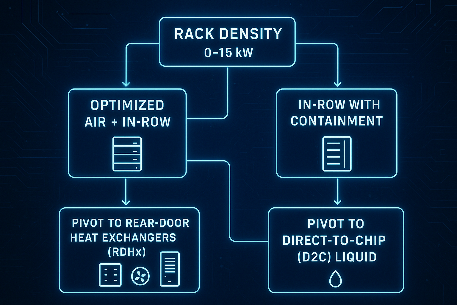
Pivot points to RDHx or D2C
In-row is often a strong bridge technology for AI-ready rows, but you should set explicit pivot points so you don’t over-invest in airflow when the physics is trying to move you to liquid.
Use this as a decision framing (validate with OEM data and commissioning tests):
Stay with in-row (air primary) when most of the heat can be moved reliably with air inside your chosen TC 9.9 envelope and when containment can keep bypass/recirculation low.
Pivot to RDHx when you need to pull sensible heat out of the rack exhaust and reduce room heat rejection burden—especially in mixed estates. For RDHx planning considerations, see Coolnetpower’s practical sizing discussion in “How much heat can a rear-door heat exchanger remove?”.
Pivot to D2C liquid when a significant share of rack power is on accelerators and the “air path” becomes a residual requirement (electronics, comfort, minor loads) rather than the main heat transport.
A useful procurement signal: if your design requires extreme airflow rates, very low supply temperatures, and tight tolerance to recirculation to stay in envelope, you’re likely past the point where pure air-side scaling is economical.
Redundancy and failure domains
Redundancy is not a checkbox (“N+1”)—it’s a definition of what must remain inside envelope after credible faults.
For in-row designs, define failure domains explicitly:
One in-row unit failure: which racks drift, and what is the time-to-alarm?
One control/sensor failure: do units fail safe or fail unstable?
One power feed failure: does a whole side of the row degrade?
Procurement-grade questions to answer before you finalize the row:
Can you isolate an in-row unit without taking down the whole row?
What is the failover behavior of fans and valves (if chilled water)?
Are alarms and interlocks integrated with BMS/DCIM with clear thresholds?
If hybrid liquid is planned, apply the same discipline to the liquid fault domain (pumps, HX, valves, sensors). A practical reference on fault-domain thinking and isolation hardware is Coolnetpower’s CDU sizing and redundancy guide.
Airflow, Containment, Controls
Airflow and CFM-per-kW
CFM-per-kW is a helpful planning shorthand, but it’s also a trap if you treat it as universal. Real airflow requirement depends on:
allowable ∆T across IT (and how much is actually delivered at the inlet)
recirculation and bypass fraction (containment quality)
fan curve and static pressure in the row
A safer workflow is:
Choose your inlet envelope and your acceptable rack ∆T.
Design containment to minimize bypass/recirculation.
Use measured commissioning data to validate that “delivered CFM” matches your model.
Pro Tip: If you can’t measure it at commissioning (rack inlet temperatures across the row, plus unit airflow/pressure), you can’t control it in operations.
For an overview of in-row deployment patterns and practical considerations, see Coolnetpower’s guide to in-row cooling units for modern server rooms.
Hot/cold containment choices
Containment is not an aesthetic choice. It is what makes your airflow “real” instead of theoretical.
Selection logic:
Cold aisle containment helps guarantee inlet conditions when IT intakes are sensitive and you want to protect the supply air.
Hot aisle containment helps when you want stable return conditions and better separation for heat rejection, and when you need to reduce mixing in mixed-density halls.
Whichever you choose, define:
door/roof integrity (leakage paths)
pressure relief and safety (no doors that trap people)
service workflow (how technicians enter without destroying containment)
Sensing and control loops
A row designed for AI workloads should behave like a controlled system, not a set-and-forget thermostat:
Place sensors where physics happens: rack inlets, containment zones, and return air paths.
Use control loops that prioritize inlet stability over return air setpoints.
Write interlocks that explicitly define what happens during abnormal events (pump trip, fan trip, leak alarm).
Control maturity is also a compliance enabler: stable sequences and measured boundaries make 90.4 and reporting KPIs easier to defend.
Hybrid Liquid Integration
RDHx versus direct-to-chip
Both RDHx and D2C move heat into a liquid loop—but they solve different constraints.
RDHx is typically used to:
remove a large share of sensible heat at the rack exhaust
reduce the burden on room air cooling
serve as a bridge for brownfield or mixed-density estates
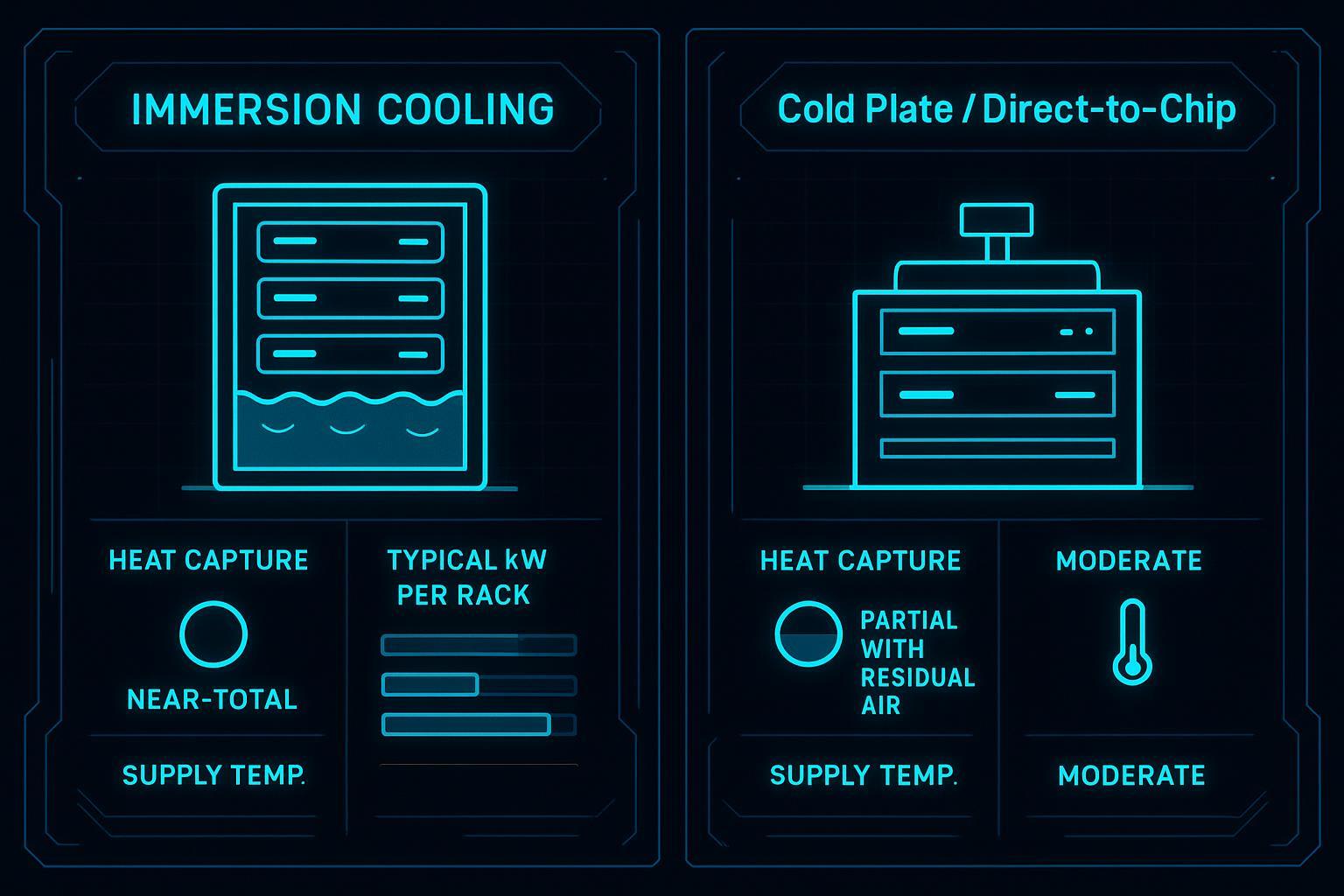
Direct-to-chip is typically used to:
target the highest heat-flux components directly
reduce reliance on extreme airflow to protect accelerators
enable higher fluid temperatures (in some designs) that improve economizer hours and waste-heat reuse potential
In practice, many AI halls become hybrid: D2C for accelerator-heavy racks, RDHx or optimized air for adjacent racks, with shared instrumentation and fault-domain boundaries.
CDU and hydraulics design
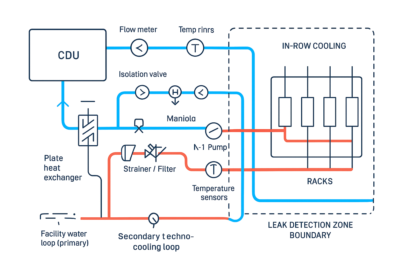
A CDU is the control point that makes hybrid liquid serviceable: it establishes a boundary between facility water and IT-adjacent loops, while giving you a place to instrument, isolate, and commission.
Design requirements to specify explicitly:
Primary/secondary separation (plate heat exchanger sizing at your expected approach temperatures)
Pump redundancy and turndown (what happens at partial load and during pump failure)
Isolation valves and bypasses (how you service without draining the whole system)
Instrumentation (supply/return temps, flow, differential pressure) and where those signals land (BMS/DCIM)
Coolnetpower integration note (under 30 words): Coolnetpower provides reference designs for in-row + CDU integration—prioritizing loop decoupling, serviceable isolation valves, and testable instrumentation to reduce commissioning risk.
For practical sizing and integration workflows, see Coolnetpower’s step-by-step guide to sizing a CDU for AI data centers and its companion guide on CDU facility loop integration essentials.
Water quality and leak detection
Water quality and leak response are not “later.” They define reliability and operating cost.
Water quality program (baseline):
Define coolant type and treatment requirements up front (including inhibitor strategy if glycol is used).
Specify filtration and differential-pressure monitoring so you can detect fouling before flow is impacted.
Include sampling points and a commissioning flush/fill plan.
Leak detection and response design:
Zone the row so a single leak does not become a hall event.
Define automatic actions (alarm-only vs isolate vs shut down) based on the risk tolerance and equipment sensitivity.
Test the leak-response sequence as part of commissioning, not after go-live.
Commissioning and Verification
CFD and heat-load tests
Treat CFD and field testing as complementary:
Use CFD to validate containment integrity, predicted recirculation risks, and sensor placement.
Use heat-load acceptance tests to prove real behavior (rack inlet stability, time-to-alarm, and recovery time) under credible load steps.
Acceptance tests should be written so procurement and operations can agree on “pass/fail,” including:
inlet temperature distribution across the row
response time to step changes
fault scenario behavior (one unit out, one pump out)
Economizer modes and sequences
Economizers are only valuable when sequences are stable across seasons and part-load. For hybrid rows:
Verify switchover logic doesn’t cause hunting (rapid toggling) in borderline conditions.
Confirm you can maintain dew point margins when supply temperatures change.
Document setpoints and deadbands so the operating team can explain performance (and avoid “mystery tuning”).
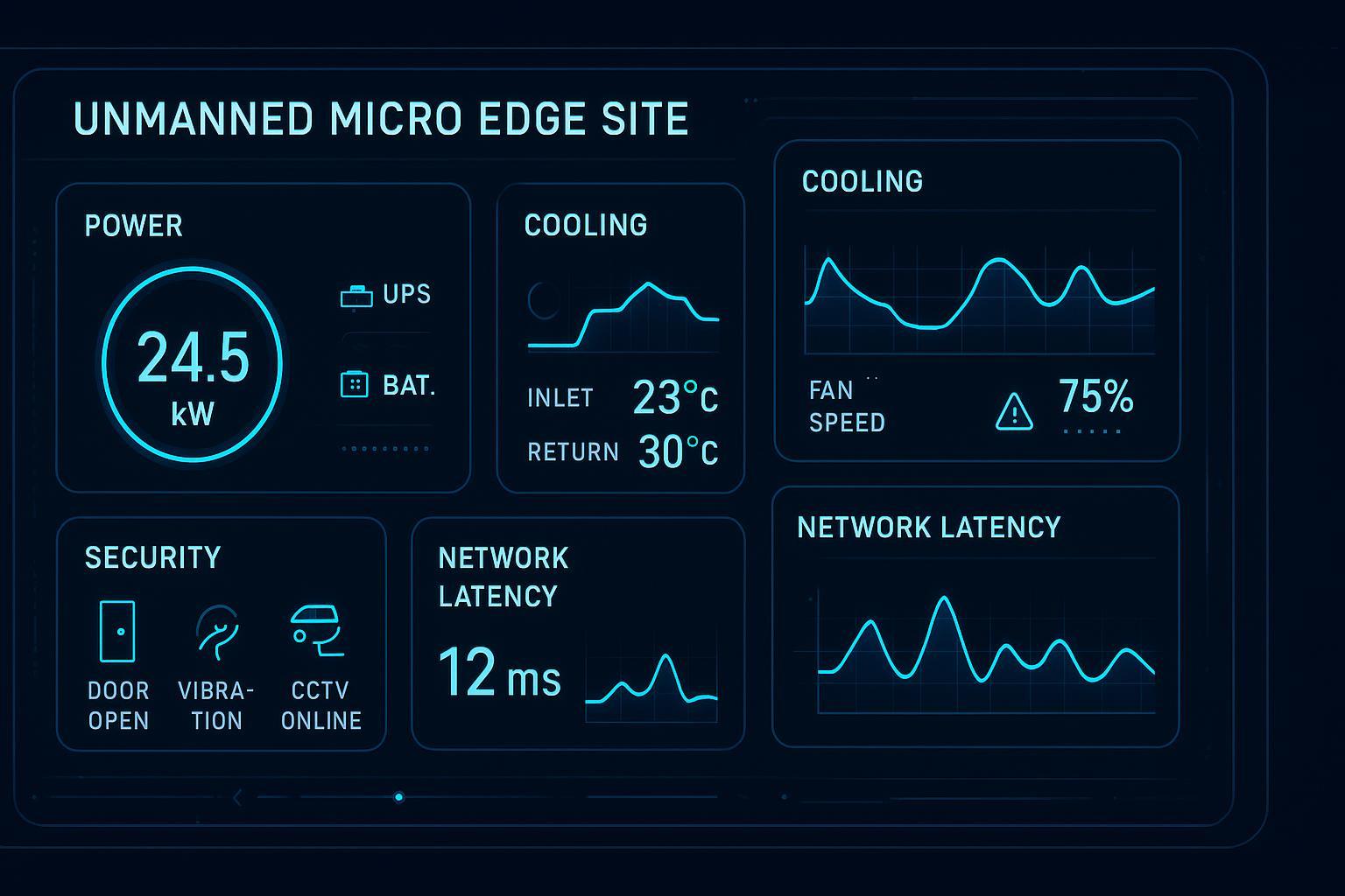
Metering for PUE/WUE/EED
If you want to report efficiency credibly, define metering boundaries at design time:
IT load boundary (what counts as IT vs infrastructure)
mechanical sub-metering (row-level if possible for comparative pPUE)
water usage measurement where applicable (especially if evaporative systems are involved)
The goal isn’t just dashboards—it’s defensible reporting aligned to your jurisdiction’s reporting framework.
Conclusion
In-row cooling remains a pragmatic strategy for AI-ready rows when you need close-coupled control, clear failure domains, and fast commissioning—without committing every rack to liquid on day one.
Action checklist for in-row cooling selection:
Confirm the target thermal envelope at the IT inlet (ASHRAE TC 9.9) and write it into acceptance tests.
Define rack power basis (sustained + 95th + fault case), not just nameplate.
Choose containment first, then size airflow and controls around delivered inlet conditions.
Define failure domains (unit, power feed, controls) and validate time-to-alarm.
If hybrid liquid is in scope, define the CDU boundary, isolation hardware, and instrumentation early.
Define metering boundaries that support PUE/WUE reporting and future EED disclosures.
Risk controls to eliminate hotspots sustainably:
Row-level sensing at rack inlets (not room averages)
Containment integrity verification + periodic audits
Explicit sequences for part-load and fault cases
Commissioned alarms that operators trust (and that don’t flood)
Compliance mapping to ASHRAE, EN 50600, and EED:
ASHRAE TC 9.9: inlet-based environmental envelope definition
ASHRAE 90.4: efficiency framed as MLC/ELC performance, not just headline PUE
EN 50600/EED: operational readiness that depends on metering, documented processes, and reportable KPIs
Next step (low friction): If you want, share your target rack kW band and redundancy requirement, and we’ll return a row-level commissioning checklist and a metering boundary sketch you can hand to EPC and operations.