Integrating a coolant distribution unit (CDU) into a facility water system isn’t “just piping.” It’s a boundary design problem: you’re coupling a data hall’s technology cooling system (TCS) to a plant-facing facility water system (FWS) — and the failure modes (low ΔT, unstable control, condensation risk, unclear redundancy behavior) only show up when you commission.
This step-by-step guide walks through hydraulics, ΔT targets, redundancy (N+1), bypass strategies, commissioning tests, and controls integration. It’s written to be vendor-agnostic, procurement-friendly, and verifiable — with typical target ranges clearly labeled as assumptions.
Key takeaway: A “successful CDU integration” is one where (1) the boundary between FWS and TCS is explicit, (2) flows are hydraulically decoupled, (3) ΔT targets are enforced by control logic (not hope), and (4) redundancy and alarms are proven under test.
Table of Contents
ToggleKey takeaways
Treat the CDU as the interface between facility water and a controlled secondary loop. CDUs are commonly described as exchanging heat between a Facility Water System (FWS) and a Technology Cooling System (TCS), creating an isolated loop where temperature, pressure, and flow are tightly controlled (Vertiv explains this model in its CDU overview).
Use a decoupled hydronic architecture so the plant can do plant things and the racks can do rack things — without fighting each other.
Use typical temperature/ΔT ranges as starting points, then lock final setpoints to OEM curves and site condensation limits.
Design N+1 at the right layer (pumps, CDUs, headers) and test failover as part of acceptance.
Commissioning is where integration succeeds or fails; Uptime Institute notes CDUs can complicate commissioning because they couple facilities and IT in new ways (see their note on commissioning complexity).
Step 0 — Define the scope of your CDU facility loop integration
Before you draw a single line on a P&ID, lock these inputs:
IT-side cooling mode: direct-to-chip, immersion, rear-door HX + liquid, or hybrid.
Target rack density band (even as a range): the hydraulics and redundancy domains change when you move from “pilot row” to “pod.”
Facility loop type: chilled water (CHW), condenser/dry-cooler loop, glycol loop, or warm-water loop. If you’re not sure, use the “generic reference architecture” in this guide and adjust setpoints later.
Reliability target: what does “redundant” mean for your site — N, N+1, 2N, concurrent maintainability, fault tolerance?
Controls owner: who owns the sequences and alarms — BMS, DCIM, or a dedicated PLC layer? (This affects point mapping and acceptance tests.)
Step 1 — Define the boundary: FWS vs TCS and what must stay isolated
Input: your facility loop definition + the CDU type you’re deploying.
Action: Write a one-paragraph boundary statement that answers:
What is “facility water” (FWS) in your project?
What is the “technology cooling system” (TCS) loop serving the racks?
Where is the heat exchanged (plate HX in a liquid-to-liquid CDU, or other boundary)?
Why: The CDU is commonly treated as the point where heat is exchanged between FWS and TCS. That boundary is what lets you control chemistry/cleanliness on the IT side and keep plant disturbances from propagating into racks.
Output: a boundary statement + a P&ID note: “FWS and TCS are isolated; no direct mixing.”
Done when: the boundary is visible in the single-line diagram and agreed by facilities + IT + commissioning.
Step 2 — Choose a reference hydronic architecture that keeps flows independent
Input: required heat rejection (kW) and your facility loop type.
Action: Choose a decoupled architecture that prevents “flow coupling” between plant and racks.
A practical default is primary/secondary decoupling:
FWS loop is controlled by the plant (often variable flow).
TCS loop is controlled by the CDU/pumps serving racks.
The interface is a heat exchanger + control valve strategy so neither side forces flow on the other.
What to watch: low ΔT is often treated like a “pump problem,” but it’s usually a system/control problem. Treat low-ΔT risk as a design issue (valves, bypass, control logic, coil selection), not as a reason to brute-force higher flow. (For a hydronics perspective on low-ΔT syndrome as a system issue, see this discussion: Avoiding low ΔT syndrome.)
Output: a selected reference architecture (diagram + control intent) that shows:
pumps (duty/standby)
isolation valves
check valves
strainer/filter
flow and temperature measurement locations
bypass paths (only where necessary)
Done when: you can state, in one sentence: “If the facility loop flow changes, TCS flow remains controlled; if TCS flow changes, facility flow remains controlled.”
Step 3 — Set temperature and ΔT targets (typical ranges + assumptions)
Input: facility loop constraints + IT inlet temperature limits + condensation risk.
Action: Set initial targets for:
facility supply temperature
TCS supply temperature
design ΔT on both sides
approach temperature across the CDU heat exchanger
Typical target ranges (starting points, not promises)
These are typical in many liquid-cooling deployments, but must be validated against your OEM curves and site constraints:
Facility chilled-water supply (CHW): ~55–60°F (13–16°C) is common in many plants.
TCS supply temperature: often ~60–70°F (16–21°C) for many direct-to-chip systems that are not running “warm water.”
Facility ΔT (FWS): often designed around ~5–7°F in many plants.
TCS ΔT: often ~5–10°F depending on device limits, flow, and stability targets.
If you’re aiming for warm-water operation (e.g., ASHRAE W-classes such as W40–W45), your temperatures shift materially; Coolnetpower discusses warm-water envelopes in its modular liquid cooling guide.
Condensation / dew-point guardrail
Even in “moderate temperature” designs, condensation risk is real any time a surface drops below space dew point.
Define a minimum supply temperature setpoint or control limit based on dew point + a safety margin.
Ensure the humidity sensors and dew-point calculation method are agreed by controls and commissioning.
For a practical explanation of dew-point control vs dry-bulb in mission-critical environments, see this dew-point control overview.
Output: a one-page “Setpoints & ranges” table with:
normal / low-load / high-load values
alarm thresholds (high return temp, low flow, etc.)
whether values are fixed or reset
Done when: controls can implement the sequence without asking you what you meant by “keep ΔT healthy.”
Step 4 — Design redundancy (N+1) and bypass paths without creating low-ΔT problems
Input: reliability target + maintenance philosophy.
Action: design redundancy and bypass with failure domains.
Redundancy: where N+1 actually matters
Pumps: N+1 is common. Use lead/lag rotation and prove auto-start on failure.
CDUs: determine if redundancy is at the CDU level (N+1 units) or at the pod/row level.
Power: if the CDU has dual power inputs, define what happens on loss of one source (alarm only vs degraded capacity vs switchover).
Bypass: use it intentionally
Common bypass needs:
Minimum-flow bypass (to protect pumps and keep control stable at low load).
Maintenance bypass/isolation (to service a CDU, filter, or sensor without draining the entire loop).
Rules of thumb:
Prefer modulating bypass over fixed open bypass.
Any bypass should have a commissioning test that proves it doesn’t collapse ΔT or destabilize control.
Output: redundancy + bypass strategy captured on the P&ID with associated test cases.
Done when: you have a written answer to: “What happens to rack temperatures if one pump fails? If one CDU is isolated? If a control valve sticks?”
Step 5 — Controls integration: points list, alarm routing, and trending
Input: who owns what (BMS vs DCIM vs PLC), and what the operators need to see.
Action: define a points list and sequences before commissioning.
Minimum CDU points list (typical)
At a minimum, plan to expose these points to BMS/DCIM:
Temperatures: FWS supply/return; TCS supply/return; computed ΔT.
Flow: FWS flow (if measured at CDU); TCS flow; flow status/fault.
Pressure: supply/return pressure or differential pressure on relevant branches.
Pumps: run status, speed (if VFD), fault, runtime hours.
Valves: command and position (bypass valve, control valve).
Filters/strainers: differential pressure or “needs service” status.
Leak detection: CDU internal leak alarm; external leak zones (where applicable).
General CDU health: unit alarm/fault, communications health.
Core sequences (keep them testable)
Maintain TCS supply temperature setpoint.
Maintain TCS flow or differential pressure setpoint.
Maintain ΔT targets by minimizing uncontrolled bypass and enforcing valve logic.
Enforce dew-point protection logic to avoid condensation risk.
Alarm routing (make it operational)
Every alarm needs:
severity (critical/major/minor)
owner (facilities/IT/controls)
response time and action
Output: a signed-off “Controls Points & Alarms” sheet plus test scripts.
Done when: the commissioning agent can test every point end-to-end (sensor → controller → BMS/DCIM → alarm console → trend log).
Step 6 — Commissioning and acceptance: PFT → FPT
Input: the P&ID, sequences, and acceptance criteria.
Action: run commissioning in layers, and keep each test tied to a measurable pass/fail condition.
Pre-functional testing (PFT)
Verify installation: valve orientation, strainer access, sensor placement, labeling.
Pressure test and leak checks per project standards.
Flush and clean loops; confirm water/coolant chemistry plan.
Pro tip: Treat the IT-side loop as a “controlled fluid environment.” ASHRAE notes that with a CDU boundary rejecting to facility water, the IT-side water quality is easier to control — that’s part of why the boundary exists (see ASHRAE TC 9.9 water-cooled servers paper).
Functional performance testing (FPT)
Test under controlled conditions:
Flow and ΔT verification at low, nominal, and peak load.
Pump staging and failover.
Bypass valve operation (minimum-flow and maintenance modes).
Sensor calibration checks.
Alarm and interlock tests (low flow, high temperature, leak alarm).
Output: an acceptance report with trend screenshots, pass/fail results, and punch-list.
Done when: you can demonstrate stable operation through load ramps without control hunting — with logged evidence.
Step 7 — Validate CDU facility loop integration under real failures (IST)
Input: integrated systems test scripts, a representative load profile (or load bank), and stakeholder sign-off on what constitutes a safe state.
Action: execute a scripted IST sequence that proves the CDU facility loop integration behaves correctly under the failures you actually care about:
Loss of one TCS pump (verify standby start and stable TCS supply temperature)
Loss of facility differential pressure / unstable facility control valve behavior (verify TCS remains stable)
Communications loss between CDU controller and BMS/DCIM (verify safe state + alarms)
Dew-point excursion scenario (verify condensation-avoidance behavior)
Leak detection trip (verify alarm routing + any configured shutoff logic)
Output: evidence pack (trend logs + pass/fail record) demonstrating stability across load ramps and single failures.
Done when: the site can show objective proof (trends + logs) that the integration is stable and recoverable under the agreed failure set.
Sample Coolnetpower P&ID (illustrative)
The diagram below is an illustrative reference to show what a well-instrumented boundary can look like. It is not construction-ready and must be adapted to your site standards.
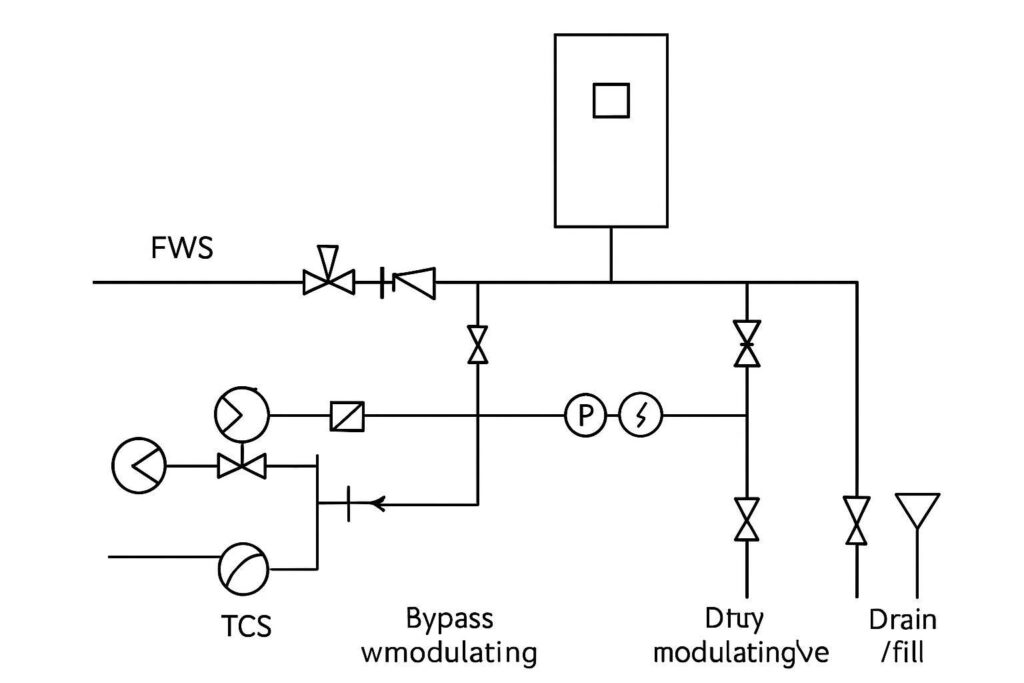
What to look for in your own P&ID
Clear FWS↔TCS boundary (heat exchanger)
Duty/standby pumps and isolation valves
Controlled bypass (not a permanent ΔT killer)
Temperature pairs for ΔT on both loops
Flow measurement where it supports acceptance tests
Leak detection zones and response logic
For broader reference designs and rollout patterns, see Coolnetpower’s modular liquid cooling guide: Meeting 50–200 kW/rack with modular liquid cooling.
Commissioning checklist (copy/paste)
Use this as a starting checklist and adapt it to your site standards.
A) Documentation and readiness
Current P&ID and single-line diagrams issued for construction
Valve list and instrument index complete
Control sequences (SOO) approved (BMS/DCIM/PLC responsibilities clear)
Alarm matrix approved (severity, routing, response)
Spares list defined (filters, seals, sensors)
B) PFT — mechanical and fluid readiness
Pressure test complete; no leaks at joints, HX plates, quick connects
Strainers/filters installed and serviceable
Fill/drain points installed, labeled, and accessible
Air purge strategy executed; no trapped air indicated by unstable flow
Water/coolant chemistry baseline established (sampling plan in place)
C) PFT — instrumentation
Temperature sensors calibrated (supply/return pairs)
Flow meter(s) verified (range, scaling, signal quality)
DP/pressure sensors verified (range, scaling)
Leak sensors tested (wet test) and alarm routed correctly
D) FPT — operating modes
Normal mode: maintains TCS supply temperature setpoint
Low-load mode: maintains minimum flow without excessive bypass
High-load mode: holds setpoints without oscillation
ΔT verification: trending shows expected ΔT bands (per design assumptions)
E) FPT — redundancy and fault response
Pump failover: duty pump failure triggers standby start within required time
CDU isolation: isolate one CDU (if N+1 topology) and confirm remaining capacity behavior
Loss of comms: safe state + alarms
Power event (as applicable): verify behavior on loss of one feed
F) IST — integrated behavior
Plant interactions: facility flow/valve changes don’t destabilize TCS control
Dew-point excursion test: system raises supply temp / triggers alarm per SOO
Alarm storm test: operators can distinguish critical alarms from advisory
Trending and historian: key points logged at agreed intervals
G) Handover
As-builts delivered
Commissioning report delivered (data + pass/fail)
Operator training completed
MOP/SOP for leak response, filter service, and setpoint changes delivered
Common failure modes (and what to check first)
Low ΔT on facility side
Check bypass valve behavior, control valve rangeability, sensor placement, and balancing.
Unstable temperature control (hunting)
Check PID tuning, sensor lag, and whether plant control conflicts with CDU control.
Condensation alarms or visible sweating
Verify dew-point calculation inputs and minimum setpoint enforcement.
Frequent pump alarms or cavitation
Check NPSH margin, air in loop, strainer clogging, and minimum-flow logic.
Leak alarms that aren’t actionable
Tighten alarm matrix: zone mapping, response procedure, and escalation.
Next steps
If you want a practical review pack for your project, Coolnetpower can provide a controls points list + commissioning checklist aligned to your site standards, and help you validate a CDU-to-plant P&ID before field cutover.
Explore Coolnetpower’s liquid cooling portfolio: liquid cooling solutions
Related reading: How to size a CDU for AI data centers step by step