Introduction
AI compute density is rising faster than most facility cooling roadmaps. In 2025–2026, the constraint isn’t only how many GPUs you can buy—it’s how much heat you can move, how predictably you can move it, and how safely you can operate when load swings are aggressive.
That’s why cooling has become decisive. At higher density, the failure mode changes from “the room runs warm” to “the cluster throttles,” “hot spots appear under transient loads,” and “operations loses confidence in the environmental envelope.”
Cold plate liquid cooling (often called direct-to-chip liquid cooling) addresses this by taking heat off the CPU/GPU package with a liquid-cooled heat exchanger (the cold plate), then transporting that heat through a controlled liquid loop to the facility heat rejection system. It sits between two familiar extremes:
Air cooling (room- or row-based airflow) that becomes increasingly constrained as density climbs.
Immersion cooling (submerging servers in dielectric fluid) that can deliver extreme density, but often demands a larger operational and supply-chain shift.
This article explains why cold plates are the most common “practical win” for high-density AI: the performance step-change over air, with a deployment and service model many operators can adopt faster than full immersion. We’ll cover the density wall, how cold plate loops work (TCS, CDU, FWS), warm-water design logic, standards alignment, and the KPI/TCO levers that help procurement and engineering stay aligned.
Key Takeaway: Cold plates are usually the fastest route to higher AI density without turning your operations model upside down.
The AI density wall
Where air taps out
Air cooling isn’t “obsolete”—it’s just a weak transport medium for the heat flux profile of modern AI racks.
As density rises, you need more airflow per rack, higher fan power inside servers, and tighter containment to prevent recirculation. The compounding effects show up as:
More fan energy and higher static pressure requirements.
Distribution bottlenecks (the air can’t get to the right place at the right pressure).
Slower response to transients, which is exactly where AI workloads punish weak control.
When operators say “air taps out,” they typically mean one of two things:
The facility can cool the room on paper, but IT component temperatures can’t stay stable at sustained utilization (throttling risk).
The upgrades required to keep air viable (containment retrofits, close-coupled systems, high fan power) erode the original simplicity advantage.
What AI racks require in 2025–2026
For high-density AI, operators need more than cooling capacity—they need predictability:
Higher heat flux at the chip (not just kW per rack).
Stable thermal headroom under long training runs and bursty inference.
A controls and telemetry model you can audit (flow, temperatures, alarms, change history).
A path to scale using repeatable pods/blocks across newbuild and retrofit zones.
Inside cold plate liquid cooling
Components and loops (TCS, CDU, FWS)
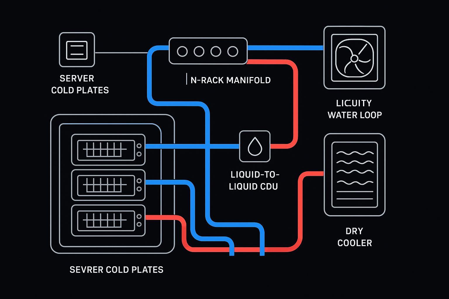
A cold plate system is best understood as two coupled loops with a clear boundary:
TCS (Technology Cooling System): the “clean, controlled” loop serving the IT equipment.
FWS (Facility Water System): the facility loop that ultimately rejects heat to ambient.
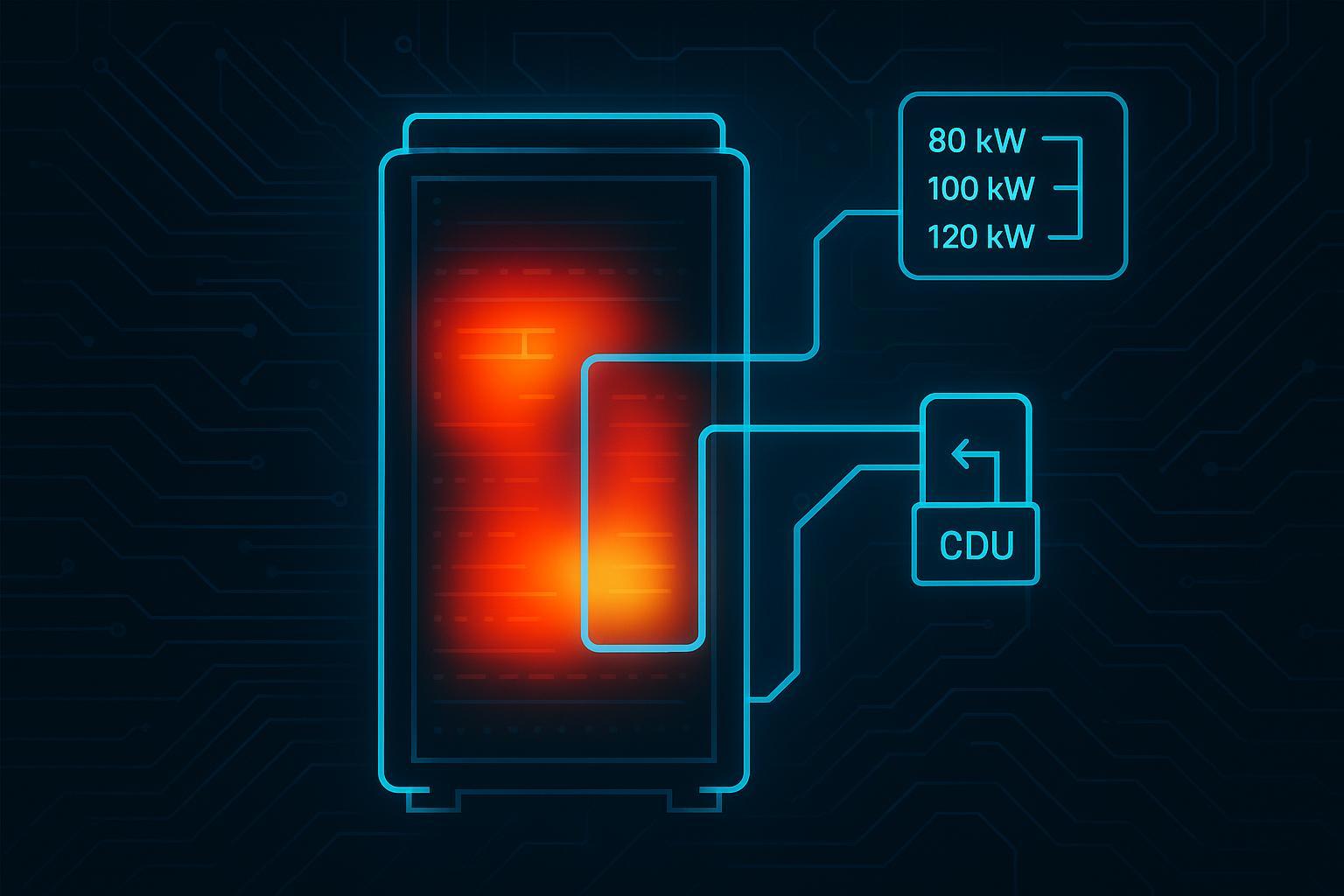
The boundary device is the CDU (Coolant Distribution Unit)—typically a pumping, controls, and heat-exchange package that decouples the technology loop from facility water quality and pressure events.
OCP’s Advanced Cooling Solutions (ACS) terminology defines TCS as the loop from the CDU through the rack manifold and IT equipment and back to the CDU, with heat transferred to the facility loop (FWS) at the boundary (see OCP ACS “Liquid Cooling Cold Plate Requirements”).
In practice, the heat path is:
chip → cold plate → rack manifold → CDU heat exchanger → facility loop → heat rejection
Capture ratio and coverage
Cold plates don’t “liquid cool the whole server.” They liquid-cool what they touch.
That’s why capture ratio matters: the percentage of total server heat removed by the liquid loop versus remaining in the air path.
Higher capture ratio reduces room heat and airflow demands.
Residual heat (memory, VRMs, storage, NICs) still needs airflow.
A well-run cold plate deployment treats this as a system boundary decision: liquid for the highest heat flux components; air for the remainder.
Warm-water and dry coolers
Cold plates can often operate with warmer coolant supply temperatures than traditional chilled-water assumptions.
Warm-water operation increases the hours where you can reject heat using dry coolers (or other economization strategies), reducing compressor run time and, in some climates, eliminating the need for mechanical chilling for the technology loop.
The caveat is condensation risk. ASHRAE TC 9.9 guidance highlights the principle of preventing condensation by regulating the technology-side supply temperature relative to room dew point (see ASHRAE TC 9.9 “Water‑Cooled Servers: Common Designs, Components, and Processes”).
Efficiency vs air and immersion
Density, PUE/pPUE, WUE ranges
Efficiency conversations around high-density AI need discipline, because the wrong metric can create the wrong incentive.
PUE is useful, but it can be distorted by accounting choices.
Many operators track partial PUE (pPUE) or subsystem metrics to isolate cooling-chain performance.
WUE is increasingly a first-class constraint in water-stressed regions.
Directionally, cold plates improve efficiency compared with air through three mechanisms:
Less fan power to move the same heat.
Higher coolant temperatures enabling more economization hours.
More stable component temperatures improving compute utilization (less throttling).
Compared with immersion, cold plates usually trade the highest theoretical capture/ceiling for a more familiar rack-and-service model.
Serviceability and retrofit fit
This is where cold plates often win on operational pragmatism:
Deploy within standard rack footprints.
Stage retrofits by row/pod rather than converting an entire hall.
Keep maintenance workflows closer to existing “rack service” culture.
If your team needs a neutral explainer of the options and where each fits, Coolnetpower’s comparison of direct-to-chip vs immersion for edge AI GPUs is a useful framing reference.
Deployment, reliability, and standards
Retrofit vs greenfield patterns
Cold plate deployments usually show up as:
Retrofit zones: high-density pods for AI racks; legacy rows remain on air or hybrid methods.
Greenfield blocks: repeatable liquid-first modules with standardized CDU sizing, manifold layouts, and monitoring points.
The strongest programs treat the “pod” as the product: a block you can replicate without re-litigating every interface.
Resilience, leak mitigation, chemistry
Reliability in cold plate systems is less about the cold plate itself and more about the system behaviors you engineer and operate.
Leak risk is real—and manageable with industrial discipline:
demarcate loops,
monitor flow/pressure/temperature,
design isolation and drain points,
implement leak detection where it matters,
and commission like you mean it.
ASHRAE guidance also distinguishes facility loop vs technology loop practices (including telemetry and condensation control), and discusses the importance of coolant chemistry and wetted material considerations in successful deployments (linked above).
⚠️ Warning: Many “liquid cooling failures” are really water quality, materials compatibility, or commissioning failures—not fundamental limits of cold plate cooling.
ASHRAE/OCP alignment
Standards alignment matters because it turns “this vendor’s system” into “a system class your organization can govern.”
ASHRAE TC 9.9 provides widely used guidance for mission-critical environments, including practical best practices for water-cooled server deployments.
OCP ACS helps normalize terminology and architecture boundaries (TCS/FWS/CDU), reducing friction in multi-vendor planning.
This is also where integrated execution capability becomes valuable. Real-world success depends on joining design intent to commissioning evidence:
Design: define the pod (density band, capture ratio target, loop temperatures, redundancy).
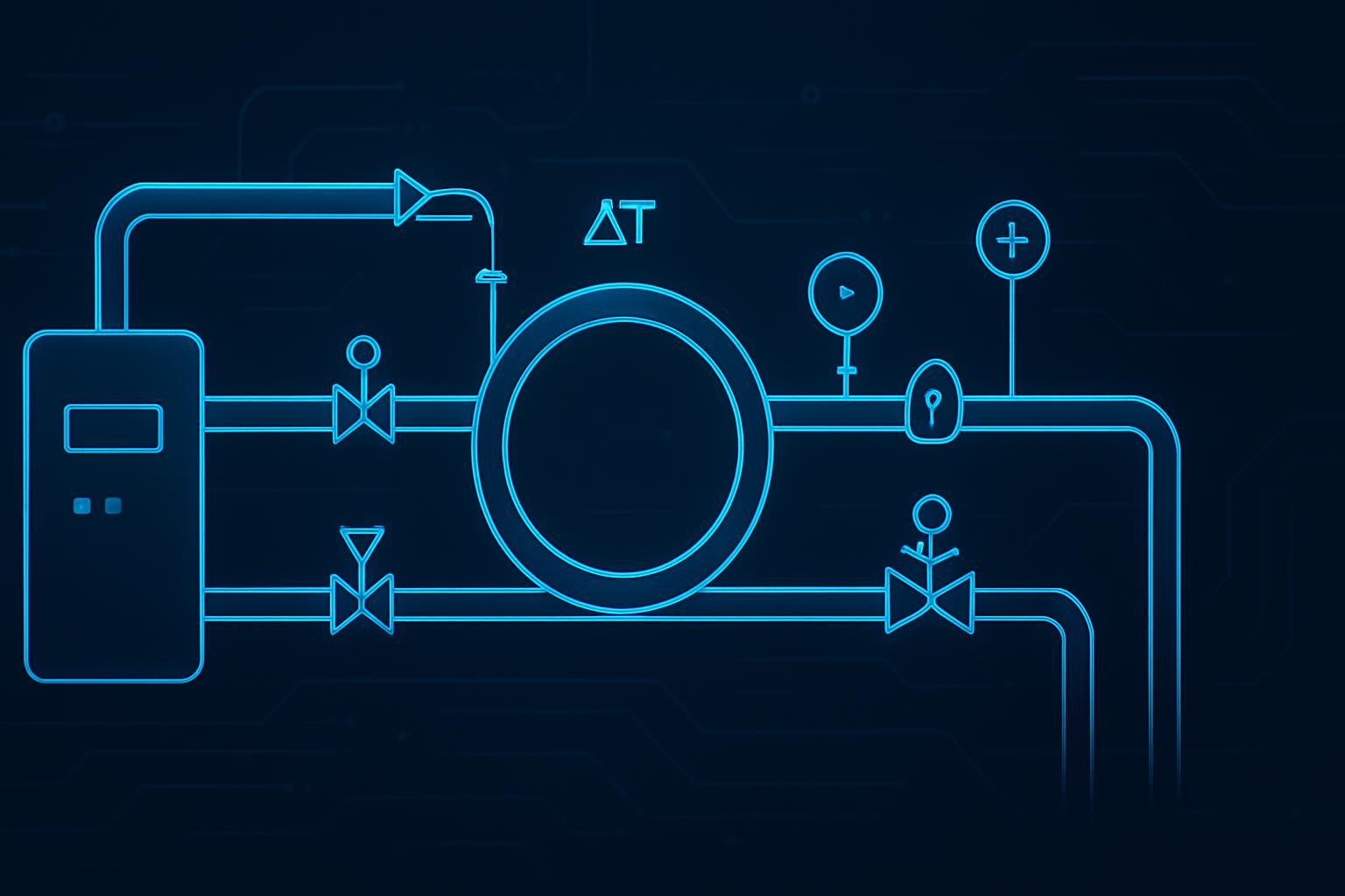
CDU integration: align flow, ΔT, approach temperature, and controls with IT requirements and facility heat rejection.
Monitoring: instrument the right points (flow, ΔP, supply/return temperatures, leak detection) and integrate alarms into BMS/DCIM.
Coolnetpower positions its work around that integrated chain—design through CDU integration and monitoring—rather than treating “cold plates” as a standalone part. For a practical operator-facing orientation, see Coolnetpower’s direct-to-chip cold plate primer.
Economics and KPIs
Energy, water, space, maintenance
Cold plate economics usually come from a bundle of improvements:
Energy: less fan power and fewer compressor hours (when warm-water economization is feasible).
Water: more hours on dry coolers (or less evaporative rejection) improves water risk posture.
Space: higher density reduces white space consumed per MW of IT.
Maintenance: shifts from air-path tuning toward liquid-loop discipline (filters, sensors, leak drills).
TCO inputs and model levers
A useful 10-year TCO model should make assumptions explicit:
density distribution and duty cycle,
heat rejection choice (dry cooler vs tower vs chiller hours),
energy and water price escalation,
staffing and training (liquid operations readiness),
maintenance plans (filters, sensor calibration, pump spares),
downtime risk and SLA exposure.
Operability metrics to track
For high-density AI, operability KPIs should make failure modes visible early:
throttling events tied to thermal telemetry,
TCS supply/return temperatures and ΔT stability,
flow and differential pressure trends,
dew point margin,
alarm quality (false positives vs actionable alerts).
Conclusion
Cold plate liquid cooling wins in high-density AI not because it’s perfect, but because it’s adoptable:
It removes heat at the chip, where the thermal problem is most acute.
It reduces dependence on extreme airflow and the fragility that comes with it.
It supports warm-water operation and dry-cooler strategies that can improve energy and water outcomes.
It aligns with standards vocabulary (TCS/FWS/CDU) and the operational reality that reliability comes from instrumentation, commissioning, and chemistry discipline.
Action checklist for 2025–2026 pilots:
Baseline the rows where you see throttling or containment instability.
Pick a pilot pod and define success metrics (dew point margin, ΔT stability, alarm acceptance).
Standardize interfaces early: TCS vs FWS boundary, CDU redundancy approach, manifold/QD conventions.
Write the ops playbook before go-live (leak response, isolation, filters/sensors cadence).
If you want a low-friction starting point, request a commissioning checklist and a basic requirements template for your density band, then run a measured pilot before scaling.