Table of Contents
ToggleIntroduction
This playbook covers end-to-end micro data center deployment for AI-ready edge data center use cases in the US and EU. It assumes you’re delivering repeatable blocks of capacity across multiple jurisdictions, often with unmanned sites and a mix of telco, wholesale, and enterprise edge workloads.
The goals are straightforward: resiliency that matches the workload, compliance that survives audits, predictable timelines that don’t fall apart on long-lead electrical gear, and KPI-driven delivery you can defend in steering committees.
Throughout, the north star is micro data center deployment that is repeatable, standards-aligned, and testable. If a decision can’t be expressed as a requirement, a drawing, or an acceptance test, it will turn into schedule slip or operational fragility later.
Key Takeaway: Treat every site as a “product release”: standardized design, controlled variants, and the same acceptance evidence package every time.
Standards and Compliance
Micro data center deployment programs tend to fail on the basics: inconsistent reference stacks, non-standard acceptance evidence, and AHJ surprises that were never modeled. Standardization here is a delivery accelerator, not bureaucracy.
Selecting the reference stack
Pick one reference stack for facilities and one for information security, then map the crosswalk once. Without a consistent baseline, different EPCs and local teams will interpret “Tier III-like” or “secure-by-design” differently.
For the EU, EN 50600 is a common facility reference because it covers availability, physical security, and energy efficiency concepts in a way procurement and auditors recognize. For US deployments, local codes drive what you can build and energize, but your resilience targets are often expressed using Tier-style outcomes or internal corporate standards.
On the energy side, EU sites increasingly need to operate as “reporting-ready.” The European Commission’s page on energy performance of data centres under the Energy Efficiency Directive is a useful anchor for what metrics and evidence are expected over time, even if your specific site sits below a threshold.
Documentation and acceptance
Define the documentation set before you release POs. The goal is to make acceptance evidence portable across sites and vendors.
Minimum acceptance package, standardized across all deployments:
Owner’s project requirements (OPR) with explicit availability and latency assumptions
Basis of design (BOD) including power single-line, network topology, and cooling architecture
Commissioning plan with roles, boundaries, and witness requirements
Factory and site test scripts (FAT/SAT/IST) with pass/fail criteria
As-built drawings and redlines as a deliverable, not an afterthought
O&M manuals, spare parts list, and maintenance procedures
Security evidence: access control model, logging, key management, and audit trail approach
A practical discipline: treat “go-live” as conditional on closing out test exceptions. If you accept exceptions informally at Site A, they become the baseline at Sites B through N.
Permitting and AHJ touchpoints
Permitting isn’t a single milestone; it’s a sequence of touchpoints with the Authority Having Jurisdiction (AHJ) and utilities. For micro data centers, the fastest path is usually to standardize the design and vary only what the locality forces you to vary.
US sites typically center on electrical and fire compliance, with permitting and inspection anchored in frameworks such as NFPA and the National Electrical Code (NEC). EU sites often combine local building/utility requirements with expectations around energy performance measurement and disclosure.
Build an “AHJ packet” that’s the same everywhere:
Site plan and one-line diagram
Fault current and protection coordination summary
Fire/life safety narrative (including suppression approach)
Acoustic and emissions statements for gensets where applicable
Environmental/water narrative if heat rejection uses evaporative cooling
⚠️ Warning: If you wait to engage the utility and AHJ until after design freeze, you will redesign under schedule pressure. Start pre-application conversations while the module is still configurable.
Siting and Network
An AI-ready edge build is only as “edge” as its measured round-trip performance and its physical route diversity. Treat latency and fiber design as first-class siting constraints, not network-team details.
Latency-driven site scoring
Start with a latency budget that reflects the application. “Edge” only matters if the end-to-end path stays inside the budget once you include transport, peering, security inspection, and application processing.
A practical approach is to define:
Latency target (e.g., sub-10 ms round-trip for many edge scenarios)
Jitter tolerance and packet loss tolerance
Measurement method (synthetic probes from user/device regions, not just lab tests)
Acceptance test (pre-go-live network validation on the final circuits)
Then score candidate sites against the budget using repeatable inputs: distance to served populations, hop count, peering options, and the expected variance under congestion.
Fiber diversity and interconnects
Treat fiber diversity as a gate, not a line item. “Two circuits” is not diversity if they share the same conduit, meet-me room, or regional aggregation point.
Minimum design questions for each site:
Are the two paths physically diverse for a meaningful portion of the route?
Are the carriers operationally independent (separate NOCs and maintenance windows)?
Is there a credible alternative interconnect (IXP, carrier hotel, or regional hub) if one provider degrades?
Where sites are unmanned, assume mean-time-to-repair is longer and design for graceful degradation: segmented services, controlled shedding, and a clear “degraded but safe” mode.
Power and environmental constraints
In edge rollouts, power is both capacity and schedule risk. Your deployment playbook should treat utility interconnect as a project track with the same discipline as factory build.
Practical siting constraints to capture early:
Utility capacity and timeline realism (not just “available”)
Redundancy options (dual feeds, on-site generation allowances)
Noise and emissions constraints for generators
Local climate and heat rejection feasibility
Water availability and any restrictions that affect WUE strategy
EU deployments also need a stronger measurement posture even for smaller sites, because sustainability reporting requirements and stakeholder scrutiny tend to tighten over time.
Power Architecture
In micro data center deployment, power architecture decisions lock in more schedule risk than most teams expect. Define the power path around the densest racks you expect to deploy, then prove it with commissioning scripts. If you design for “average racks,” AI racks will force late changes in distribution, heat rejection, and generator strategy.
Rack density and distribution
Define rack density bands up front and design distribution so the densest racks don’t force a full-site redesign.
A common pattern in AI edge builds is mixed density:
“General compute” rows at moderate density
A smaller number of AI racks that drive peak power and thermal requirements
Distribution decisions that are hard to change later:
Voltage strategy to the row/rack n- Busway vs whips
Space allocation for PDUs, RPPs, or in-rack power shelves
Metering granularity (site, room, row, rack) for KPIs and reporting
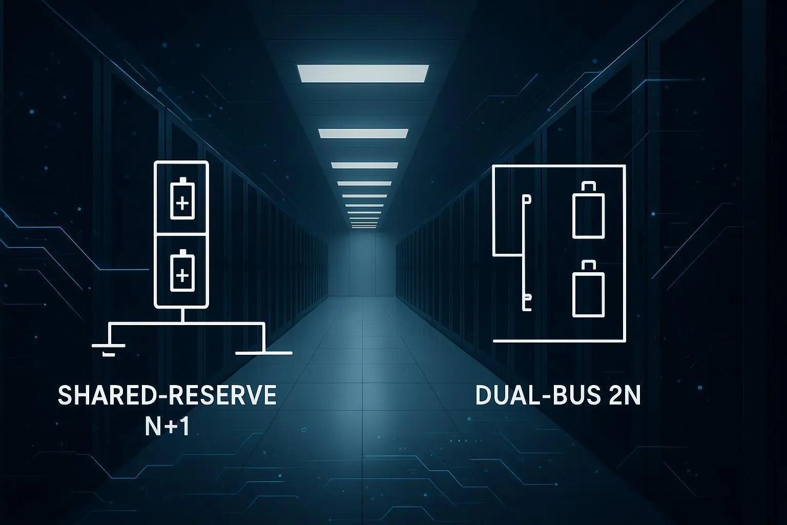
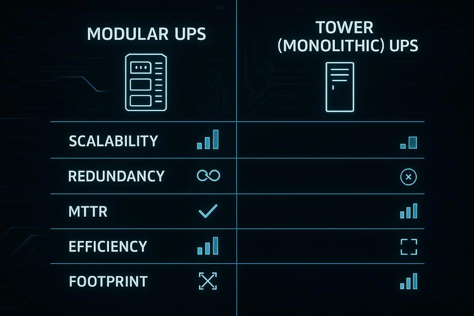
Redundancy and availability targets
Use redundancy targets deliberately. N, N+1, and 2N aren’t badges; they’re trade-offs.
N can be acceptable for low criticality or when redundancy is provided upstream.
N+1 is a common balance point for modular power trains and generator capacity.
2N is typically reserved for workloads that must ride through a single failure and maintenance without customer-visible impact.
Make the target measurable: define the allowed outage types (planned vs unplanned), maximum interruption time, and what “available” means for the service (power on rack isn’t enough if the network path is down).
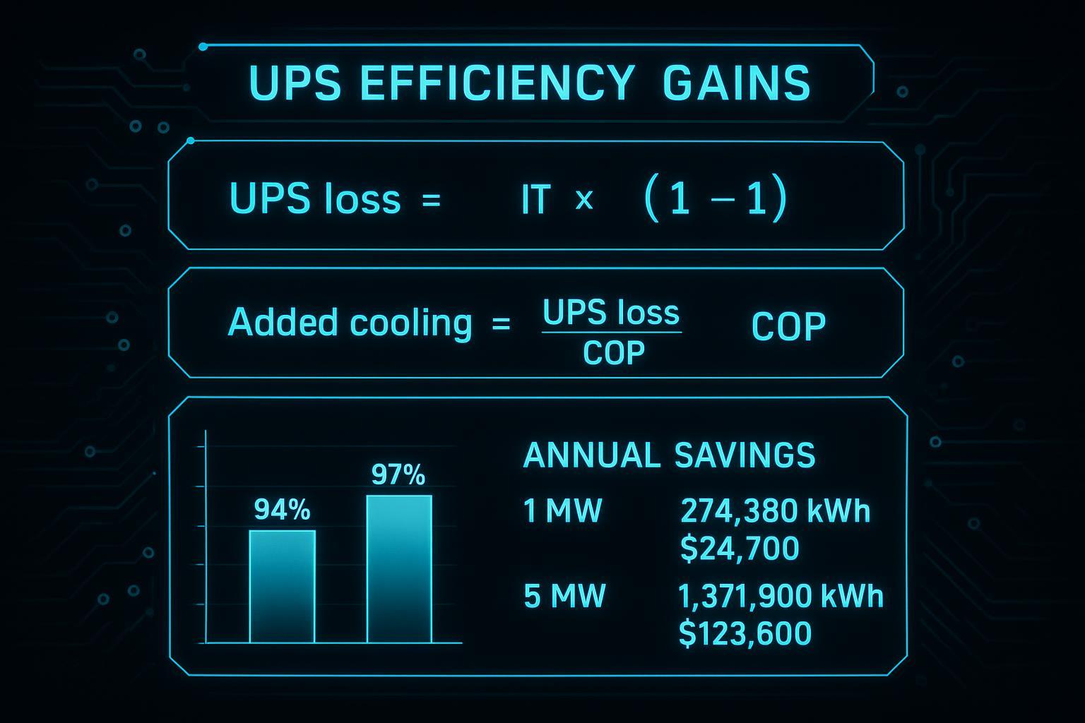
UPS, gensets, and long-lead strategy
Electrical long-lead items routinely define the critical path. In US/EU modular deployments, the usual suspects are transformers, switchgear, UPS systems, and generators.
Long-lead mitigation that scales across many sites:
Freeze the single-line and redundancy model early enough to place binding orders
Standardize on a small number of module SKUs to avoid custom engineering per site
Use frame contracts where possible to stabilize lead times and pricing
Plan “bridging” options explicitly (temporary power, staged load-in, phased commissioning)
The operational reality: an AI-ready edge site with high-density racks doesn’t fail gracefully when power is unstable. Invest in power quality and protection coordination early, then prove it in acceptance testing.
Cooling for AI Readiness
For AI loads, the question isn’t “can we cool it in steady state?” It’s “can we cool it through transients, service events, and alarms, with the site unmanned?” The answer has to be visible in your architecture and test scripts.
Air, RDHx, and direct-to-chip
For AI readiness, cooling is about matching heat removal to rack density without turning operations into hero work.
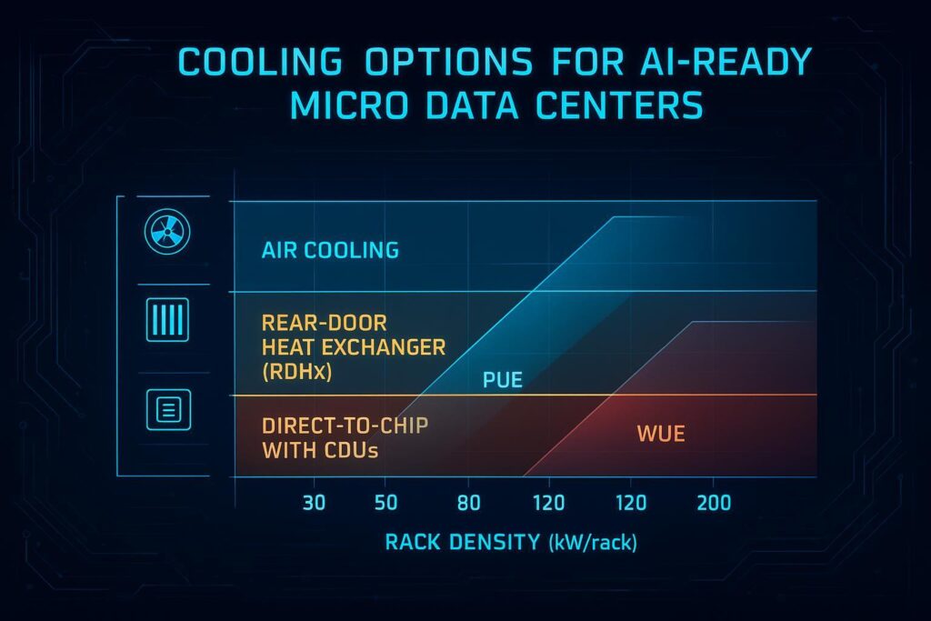
A useful selection lens is density bands:
Air cooling tends to fit lower densities, especially where containment and airflow management are mature.
Rear-door heat exchangers (RDHx) are a pragmatic midpoint when you want to keep the server largely air-cooled but pull heat at the rack boundary; Supermicro’s definition of rear door heat exchangers (RDHx) is a clear reference for what the technology is and why it’s used.
Direct-to-chip becomes relevant as you move into sustained high-density AI racks where airflow alone is no longer credible.
Engineering considerations that often get missed in early design:
CDU placement and serviceability: define where the CDU lives (in-row, adjacent technical space, or centralized skid), how you isolate it, and what “maintenance without outage” means.
Secondary loop definition: specify supply temperature window, approach temperatures, and minimum flow rates per rack/zone.
Compatibility and quick disconnect discipline: standardize connectors and define procedures for install, drain/fill, and servicing.
This is also where modularity matters. For example, Coolnetpower (as a capabilities set rather than a product pitch) supports deployments that combine modular micro data center blocks with liquid-cooling modules, enabling a repeatable pattern: standardized piping and monitoring at the module boundary, then controlled variants based on whether a site is air-only, RDHx-assisted, or direct-to-chip.
The technical value is in reducing integration risk: you want the same leak detection approach, the same sensor naming, the same alarm thresholds, and the same isolation points across every site.
Heat rejection choices and water use
Heat rejection is where PUE and WUE become real, site-specific engineering decisions.
Early questions to resolve:
Do you reject heat via air-cooled heat exchangers/dry coolers, a chiller plant, or evaporative systems?
What is the year-round ambient profile, and what does it do to approach temperatures?
If you use evaporative heat rejection, what is the water supply and what are the constraints (cost, restrictions, community acceptance)?
In the EU, WUE discipline often matters as much as PUE discipline because water constraints and disclosure pressure can be the gating factor for expansion.
Leak management and monitoring
Leak management is an operational design problem, not an afterthought.
Define, test, and document:
Leak detection method (point sensors, rope sensors, differential pressure trends)
Isolation design (zone valves, dripless quick disconnects, drain points)
Alarm routing and escalation for unmanned sites
What “safe state” means (pump shutdown, rack power limit, or controlled shedding)
Most importantly: include leak scenarios in your commissioning scripts. If you only test for cooling performance, you’ll discover leak-handling weaknesses during live operations.
Modular Delivery and Commissioning
Modular delivery only stays fast if interfaces are standardized and testable. Your advantage comes from parallel workstreams and factory-level fault discovery, not from rushing site work.
Prefab schedules and parallelization
Modular delivery wins when you run factory build and site readiness in parallel, with interfaces that are tested before they arrive on site.
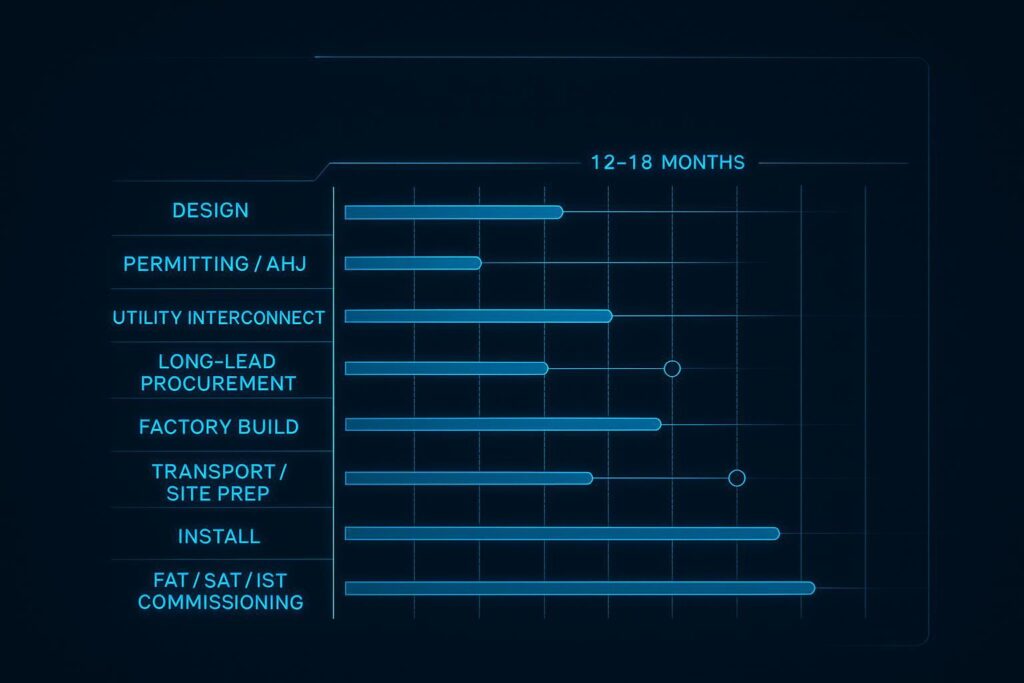
Parallel tracks to plan explicitly:
Permitting and utility interconnect
Factory fabrication and integration
Network carrier provisioning
Site civil works and foundations
Security and access control provisioning
The playbook should define what is allowed to vary site-to-site (e.g., utility voltage, local fire requirements) and what is locked (module layout, control philosophy, test scripts).
Long-lead items and early POs
If you want predictable timelines, treat early procurement as risk control, not as “starting early.” The critical items are usually in power and heat rejection.
Typical long-lead drivers:
MV/LV transformers and switchgear lineups
UPS frames, batteries, and static transfer components
Gensets and emission control equipment
Heat rejection equipment sized to the real ambient profile
Lock your long-lead list by tying it to one document: the reference single-line and mechanical schematic. If those aren’t stable, your PO strategy will thrash.
Modular micro data center commissioning: FAT, SAT, and IST scripts
Standardize scripts and require objective pass/fail criteria.
FAT (Factory Acceptance Test): validate integration, controls, alarms, labeling, and “known failure” behaviors in the factory where rework is fast.
SAT (Site Acceptance Test): validate utilities, grounding, protection coordination, and network dependencies on the real site.
IST (Integrated Systems Test): validate that power, cooling, security, monitoring, and failover work together under realistic scenarios.
In practice, IST should cover:
Utility fail and generator start/transfer
UPS bypass transitions (where relevant)
Cooling degradation modes and alarm routing
Network path failover and segmentation checks
Remote operations cutover (NOC workflows, escalation, runbooks)
Security and Operations
Edge fleets succeed when they operate like a product: consistent configuration, observable behavior, and controlled change. Security and ops tooling should be built into the reference design, then reused without improvisation.
Zero-trust and segmentation
Edge sites expand your attack surface. Treat security as a system architecture requirement, not an overlay.
Practical design moves:
Segment OT (power/cooling controls) from IT (workloads) with explicit policy boundaries
Enforce identity-based access and least privilege for operators and vendors
Make logging and time synchronization non-optional so you can reconstruct incidents
Where ISO-aligned operational controls are required, ISO/IEC 27001 is often the baseline for how you structure evidence and audits.
Physical security at unmanned sites
Unmanned sites demand layered physical security because response time is inherently slower.
Define a consistent package:
Access control with role-based permissions and audit logs
Video surveillance with retention aligned to policy
Tamper detection on enclosures, racks, and critical panels
Clear “maintenance mode” procedures so vendors don’t become a bypass
The key is operational simplicity: fewer exception paths means fewer failures during real incidents.
Remote ops, DCIM, and observability
Remote operations only work when you can see, diagnose, and act without improvisation.
Minimum observability signals to standardize across sites:
Power: per-feed and per-branch metering, UPS states, generator telemetry
Cooling: supply/return temps, flow rates, valve states, leak detection, CDU status
Network: link health, latency/jitter probes, path diversity alarms
Security: access events, camera health, config drift alerts
Even at micro scale, you want data that supports KPIs and compliance narratives. If you can’t produce consistent PUE/WUE and availability evidence, you don’t have an operational program.
Conclusion
If you want AI-ready edge capacity without chaos, build a deployment system that is explicit about KPIs and honest about constraints.
Track a small set of KPIs from the first site and keep them consistent across the fleet:
PUE/WUE bands that match your heat rejection and climate reality
Availability targets aligned to your redundancy choices (N vs N+1 vs 2N)
Latency budgets validated on production circuits, not assumed in design
Top risks tend to repeat across programs:
Siting: weak fiber diversity and optimistic latency assumptions
Utilities: interconnect delays and transformer/switchgear lead times
Cooling: density drift, under-specified CDU/serviceability, and weak leak runbooks
Supply chain: late architecture changes that invalidate early POs
Next steps that help teams move faster without taking on blind risk: request a commissioning checklist, a long-lead tracker template, or a weighted site scorecard you can reuse across US/EU deployments.