Table of Contents
ToggleIntroduction
In power design conversations, “redundancy” can sound like a simple slider you push toward “more uptime.” In practice, it’s a set of architectural choices about where you can tolerate failure, how you maintain equipment, and how much stranded capacity (and capex) you’re willing to carry.
This article focuses on three common terms used in data center power redundancy:
N: the minimum capacity you need to support the IT load.
N+1: the minimum capacity plus one shared spare.
2N: two full, independent power paths, each capable of carrying the full load.
The N+1 vs 2N choice matters because it influences:
Uptime risk: what single failures can still take down the critical load.
Cost and footprint: how much equipment, electrical room space, and distribution hardware you need.
Tier goals: how you align design intent with concepts such as concurrent maintainability and fault tolerance.
What you will learn:
Clear definitions of N, N+1, and 2N for power systems
The real trade-offs (reliability, cost, efficiency, maintenance)
How these architectures relate to Uptime Institute Tier intent
A step-by-step guide to choosing the right power tier for your project
Architectures explained
N: baseline capacity
N means you have exactly the capacity required to support the design IT load. There’s no spare module, no spare unit, and usually no way to take a component out of service without reducing available capacity.
A concrete example: if your IT load and growth assumptions require four UPS modules to support the critical load, then N = 4. If one module trips or needs replacement, you’re now below required capacity.
This is why N designs are typically limited to non-critical environments or small sites where downtime windows are acceptable.
N+1: shared reserve
N+1 adds one additional component beyond the minimum required. In the UPS example above, N+1 = 5 modules. The extra module is a shared spare that can absorb one module failure or allow one module to be serviced without dropping below required capacity.
The value of N+1 is its efficiency of spend: you’re not duplicating the entire plant, you’re buying a controlled amount of insurance.
The limitation is failure domain. If the design still has shared elements (a single bus, a single downstream distribution segment, a common transfer point, or a single point of control), N+1 at the “box level” may not eliminate single points of failure at the “path level.” That’s usually where project teams get surprised during commissioning.
2N: fully mirrored paths
2N means you build two independent power trains, each capable of carrying 100% of the critical load. Think A-side and B-side, with separate upstream sources, separate UPS capacity, separate distribution paths, and downstream equipment that can accept power from either side.
Properly executed, 2N narrows shared failure domains dramatically. It also improves maintainability: you can isolate one entire path for maintenance while the other path carries the load.
The trade-off is obvious and unavoidable: you’re buying and housing two full systems, so cost and space go up, and utilization often goes down.
N+1 vs 2N trade-offs and tiers
Reliability, cost, and efficiency
For an IDC机房项目总监, it helps to frame this as three questions:
What single event are we designing to survive?
Can we maintain equipment without taking IT down?
Do we have the space and budget to make the failure domains truly independent?
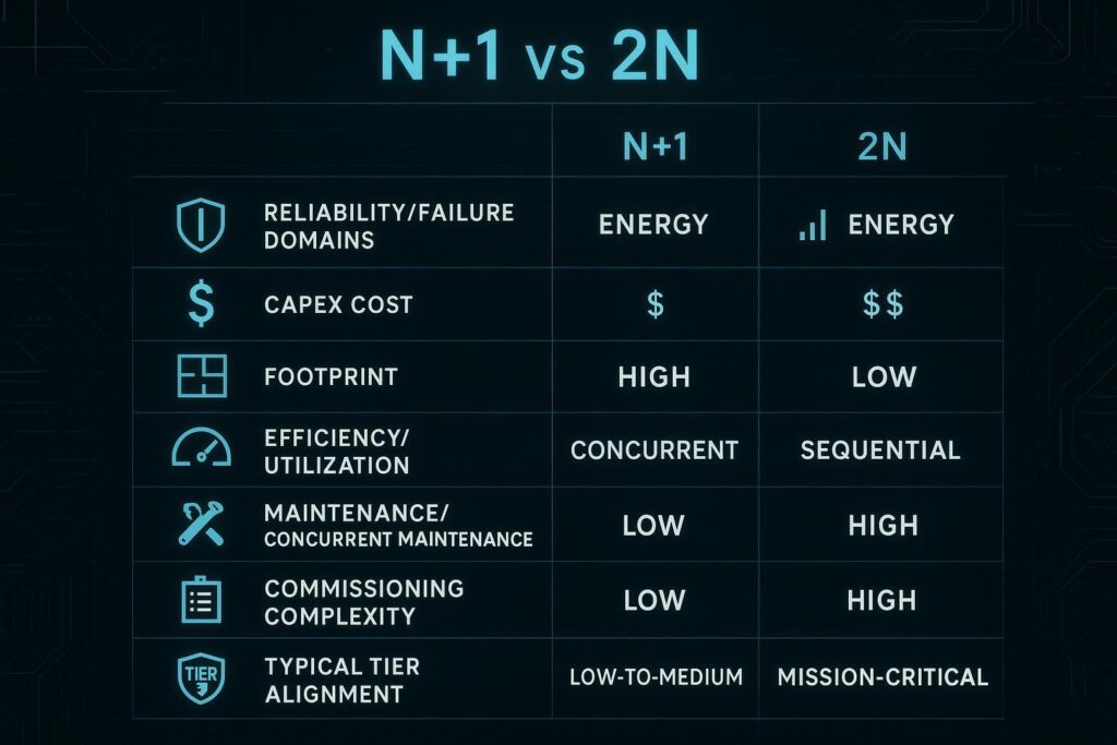
A practical comparison:
Dimension | N+1 (shared reserve) | 2N (mirrored paths) |
|---|---|---|
Reliability lens | Survives one component failure (or one maintenance event) if the shared path holds | Survives the loss of one entire power path if independence is real |
Common hidden risk | Shared downstream elements (single bus, common ATS/STS, common PDU segment) can still be a single point | Cross-ties and shared auxiliaries can accidentally reintroduce common failure points |
Capex & footprint | Moderate increase vs N; usually fits tighter electrical rooms | High increase; two paths need space, routing, and separation |
Efficiency & utilization | Often better average utilization, less stranded capacity | Often lower utilization (one side lightly loaded in normal operation), which can reduce efficiency |
Operational posture | Requires strong procedures so maintenance doesn’t stack risk (maintenance + failure) | Better for planned maintenance, but still requires disciplined switching and testing |
If you want a simple memory hook: N+1 protects a component; 2N protects a path.
Uptime Tier alignment
Tier language gets misused in early-stage projects. Uptime Institute’s core intent is not “pick a redundancy number,” it’s how the site behaves during maintenance and failures.
Tier III is defined as concurrently maintainable power intent, with redundant components and redundant distribution paths serving the critical environment. The goal is that you can take any planned component out of service without shutting down IT.
Tier IV adds fault tolerance, with independent and physically isolated systems so that a failure of equipment or an interruption in the distribution path does not affect IT operations.
That’s why the practical mapping is usually:
N aligns with Tier I-style intent (basic capacity, no redundancy).
N+1 often aligns with Tier II intent (redundant components), and can support Tier III intent when distribution and maintainability are designed correctly.
2N is commonly used to pursue Tier IV-style fault tolerance, provided the paths are truly independent and the IT load can ride through path loss.
For Tier definitions, use the original language in Uptime Institute’s Tier overview. For an accessible explanation of redundancy terms, see CoreSite’s overview of N, N+1, and 2N redundancy (2021).
Typical use cases
N+1 tends to fit when:
You can tolerate short, controlled risk windows (for example, when a spare is temporarily unavailable during maintenance).
Your electrical rooms and distribution routes are tight, and duplicating paths would force major building changes.
Your IT load is not consistently dual-corded, meaning a full 2N facility would still be limited by single-cord endpoints.
2N tends to fit when:
Downtime cost is extremely high and service credits or regulatory exposure make outages unacceptable.
You require strong concurrent maintenance capability with minimal risk stacking.
You can enforce A/B separation and have a high proportion of dual-cord IT loads that can actually benefit from two independent sources.
How to choose your power tier
Business impact and TCO
The cleanest way to choose between N+1 and 2N is to treat redundancy as an economic and risk decision, not a label.
Start with two inputs that procurement can validate:
Downtime impact: revenue loss, SLA credits, customer churn risk, regulatory exposure, and recovery effort.
Lifecycle cost: capex + space + commissioning + maintenance + energy over the period you plan to hold the asset.
Then ask one question:
If you spend the incremental capex for 2N, are you buying down a risk that actually dominates your downtime profile?
If the dominant downtime drivers are change-control failures, configuration errors, or downstream single-cord loads, a 2N plant may not deliver the risk reduction you think it does unless you pair it with operational controls and endpoint readiness.
IT load and STS strategy
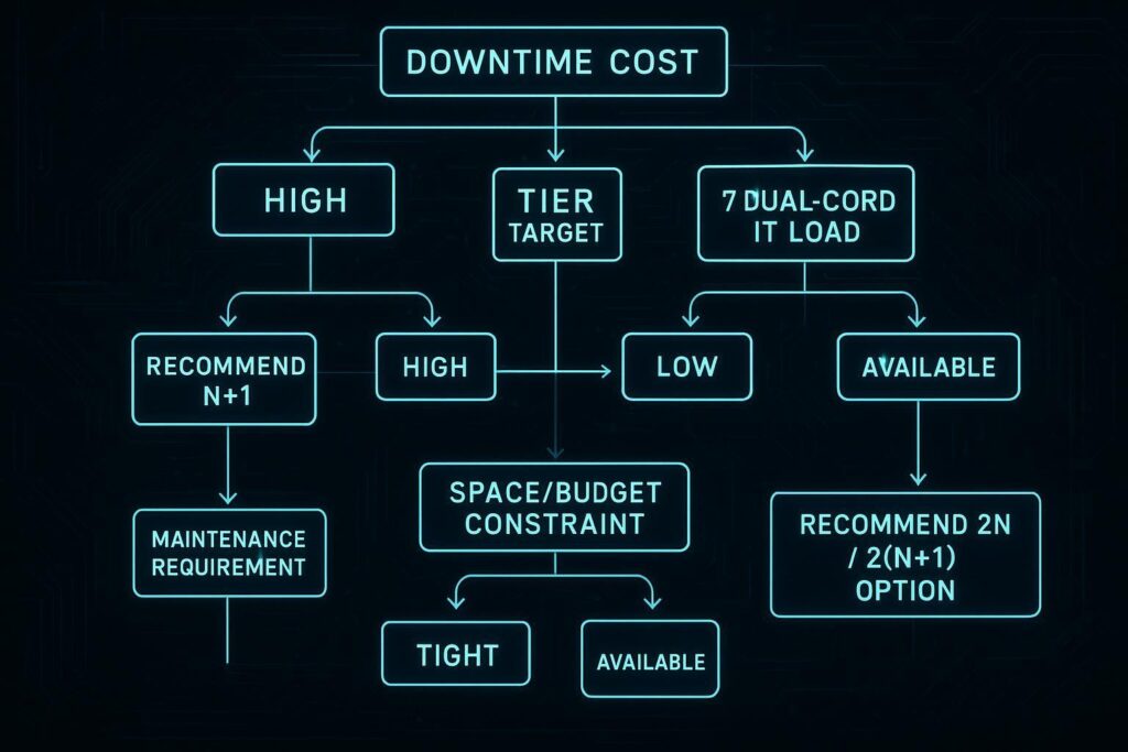
Before you commit to 2N, validate the IT side reality: what percentage of the critical load is truly dual-corded, how the STS (static transfer switch) is used (and whether it becomes a shared failure domain), and what the actual UPS/generator ride-through assumptions are.
In Coolnetpower project reviews, a common best practice is to start with a documented dual-cord ratio and STS risk register, then size UPS capacity to the redundancy objective without double-counting headroom, and validate the generator + fuel path end-to-end during commissioning.
If you want a practical sizing workflow that keeps redundancy decisions grounded in measured load and realistic growth, see Coolnetpower’s practical UPS sizing workflow.
Site constraints and growth
Even when 2N is justified on paper, site constraints can turn it into a compromised implementation:
Electrical room area and routing: true 2N wants physical separation of A and B paths. If both paths share the same room, tray, or choke point, the fault domains can merge.
Utility and generator constraints: redundant paths only help if upstream sources and transfer schemes support the intended behavior.
Phasing and expansion: N+1 can be easier to phase. If you expect rapid expansion, you may prefer modular capacity blocks so you can add redundancy as the load grows.
Two practical questions to ask early:
What is the expansion cadence (quarterly pods vs annual halls), and can your redundancy model scale without rework?
Can your commissioning and acceptance plan validate the failure behaviors you’re paying for?
For a procurement-oriented view of redundancy as a requirement (not a slogan), plus maintainability and fault-domain considerations, see redundancy as a requirement (Coolnetpower).
Conclusion
If you strip away the labels, the decision is straightforward:
N is baseline capacity with limited tolerance for failure or maintenance.
N+1 adds a shared reserve that typically delivers the best balance of resilience, cost, and footprint, but it doesn’t automatically eliminate shared failure domains.
2N mirrors the power path to reduce common failure points and improve maintainability, but it demands more space, higher capex, and disciplined A/B separation to deliver its promise.
Key takeaway on Tier nuance: Tier III is about concurrent maintainability, and Tier IV is about fault tolerance. Redundancy numbers help describe the design, but the Tier intent is proven by how the site behaves during maintenance and failures.
Next steps:
Map failure domains (what single events can still interrupt load) and align them to your SLA and compliance exposure.
Build a simple TCO model that includes space, commissioning, and operational complexity, not just equipment cost.
If you want a procurement-ready checklist for acceptance testing and maintainability, use the FAT/SAT guidance in FAT/SAT checklist considerations for modular UPS.
Key Takeaway: If you’re deciding between N+1 and 2N, start with failure domains and operating reality (dual-cord percentage, maintenance workflow), then select the architecture that removes the risks you actually have.