Table of Contents
ToggleKey takeaways
A Cooling Distribution Unit (CDU) is the control point between your facility water system (FWS) and the technology cooling system (TCS) serving liquid-cooled racks.
CDU stability is mostly about three variables: supply temperature, flow rate, and differential pressure—and how fast they change when load shifts.
Sizing isn’t just “kW capacity.” You also need a defensible ΔT target, pump head calculation (including dirty-filter pressure drop), and a redundancy plan aligned to your failure domain.
Most avoidable incidents come from basics: condensation risk (dew point), poor filtration/water quality, lack of leak detection, and weak commissioning/acceptance criteria.
Introduction
AI and HPC racks compress a lot of heat into a small footprint. Once densities climb, air becomes a “residual” path—useful for some components, but no longer the primary heat transport mechanism. That’s why direct-to-chip liquid cooling is moving from niche to mainstream for new AI buildouts and high-density retrofits.
But a liquid loop doesn’t fail gracefully. If flow drops, supply temperature drifts, or pressure oscillates, the equipment can approach thermal limits quickly. For an IDC project director, the real risk isn’t just inefficiency—it’s schedule disruption (rework), acceptance-test failures, and unplanned downtime exposure after handover.
A Cooling Distribution Unit (CDU) exists to make the loop predictable. It stabilizes temperature, flow, and pressure on the IT-side loop while isolating the facility side from the tighter cleanliness and control requirements at the rack.
This guide explains how CDUs work, what drives instability, and what to look for when sizing, deploying, and operating them—so you can specify a solution your facilities team can run and your IT team can trust.
Cooling Distribution Unit (CDU) fundamentals
Interface between facility water and IT loop
Most liquid-cooled data centers separate the building side from the IT side:
Facility Water System (FWS): the plant-side loop (chillers, cooling towers, dry coolers, pumps).
Technology Cooling System (TCS): the controlled loop that serves cold plates, manifolds, and rack distribution.
ASHRAE TC 9.9 uses this separation explicitly in its discussion of water-cooled server system design (see the ASHRAE TC 9.9 white paper on water‑cooled servers).
The practical takeaway is simple: FWS is optimized for building operations; TCS is optimized for IT protection. A CDU sits between them.
In most implementations, the CDU transfers heat across a heat exchanger so the two loops don’t mix fluid. That isolation is a reliability feature: it lets you run tighter filtration, chemistry control, and pressure limits on the IT loop without requiring the entire facility loop to meet those same constraints.
If your team is still aligning on liquid-cooling options, a quick internal primer is Coolnetpower’s overview of direct‑to‑chip liquid cooling with cold plates.
Core components and controls
Think of a CDU as the hydraulic governor and thermal “air gap” for the IT loop. Common building blocks include:
Heat exchanger (often plate type) to transfer heat between FWS and TCS.
Pumps (usually VFD-controlled) to maintain stable flow and differential pressure.
Expansion tank / reservoir to manage thermal expansion and stabilize loop pressure.
Filtration to protect cold plates and small passages from fouling.
Sensors (temperature, pressure, flow) and a controller to hold setpoints.
Valves and bypass paths for control and serviceability.
From an operator perspective, what matters is not just the presence of these components, but their control logic and service modes: can you change filters without destabilizing the loop, can pumps fail over cleanly, and can you trend the right variables in BMS/DCIM without drowning in noise.
Safety and water quality
Liquid cooling introduces failure modes you don’t see (or don’t see as fast) in air systems:
Condensation risk
If the loop supply temperature falls below the local dew point, condensation can form on cold surfaces. Several industry references describe the common practice of setting supply temperature at least ~2°C above dew point as a guardrail (see the dew point discussion in CSE’s guide to piping systems for liquid-cooled data centers).
⚠️ Warning: Dew point control is a controls problem, not just a mechanical one. Your CDU, BMS, and humidity sensing strategy must agree on how dew point is measured and how supply temperature setpoints are constrained.
Leak risk and containment
Even with dripless quick disconnects, you need leak detection and a containment plan (drip trays, zoning, shutoff logic) that matches your operational maturity.
Water quality and filtration
Cold plates and manifolds have small internal passages. Fouling, corrosion products, or biological growth can create pressure drop and reduce effective heat transfer.
Practically, “water quality” for an IDC project director translates to two things you can specify:
A sampling/monitoring plan (who measures what, how often, and what triggers action).
A filtration and maintenance plan (filter rating, differential-pressure alarms, and service procedure).
Sizing and selection
Capacity, flow, and ΔT targets
Thermal capacity (kW) is the headline number, but it’s not the full sizing story.
At a minimum, you need these three inputs:
Design heat load (kW) on the liquid loop (per rack, row/pod, or cluster).
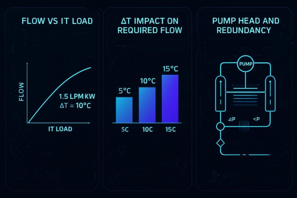
Target ΔT across the IT loop (supply-to-return) that your equipment and control strategy can sustain.
Required flow to meet that ΔT at the specified load.
A common way to keep the team aligned is to document the sizing relationship explicitly (even if vendor tools later refine it). Many operator-facing references cite order-of-magnitude guidance in the neighborhood of ~1.5–2.0 L/min per kW depending on the chosen ΔT and hardware constraints (example values appear in multiple CDU sizing discussions, including the operator framing in Equinix’s “Anatomy of a Direct‑to‑Chip Liquid Cooling System” (2026)).
What matters for stability is not hitting a single “design point,” but understanding off-design behavior:
What happens to flow when a control valve trims?
How quickly does the pump ramp on a step load?
Does ΔT remain stable across partial load and mixed rack populations?
Pump head and redundancy
Two CDUs with the same kW rating can behave very differently if pump head and redundancy aren’t aligned to the real loop.
Pump head must cover the worst-case pressure drop loop, including:
longest supply/return piping run and fittings
rack manifolds and quick disconnects
cold plate pressure drops
heat exchanger and control valve pressure drops (as applicable)
filtration pressure drop, including dirty filter end-of-life conditions
If you size only on clean-filter, short-run assumptions, you often get a loop that is stable in factory demos but oscillates or alarms in the field after months of operation.
On redundancy, be explicit about what you need to survive:
N+1 pumps usually targets single pump failure or planned service without stopping flow.
“Bigger” redundancy moves toward isolating larger failure domains (e.g., pod-level vs row-level vs room-level). The architecture choice (in-rack vs in-row vs gallery) changes the failure domain and maintenance surface area—something Vertiv highlights in its architecture overview (“Evaluating CDU architectures”).
For project delivery, the procurement-friendly move is to require:
a stated failure domain (what goes down when one CDU is out)
a stated failover behavior (what happens to flow/pressure during switchover)
a stated acceptance test for pump failover (pass/fail criteria)
Approach temperature and efficiency
Approach temperature (how close the IT-side supply temperature can get to the facility-side water temperature across the heat exchanger) is one of the most important “hidden” performance and efficiency levers.
Lower approach typically requires more heat exchanger surface area (and sometimes more pumping power). Higher approach can force you to run colder facility water than you wanted—pushing you toward chillers instead of economization.
This is where selection trade-offs show up in real projects:
If your site is aiming for warmer facility water (to enable economizers or heat reuse), you may need a CDU/heat exchanger design that maintains acceptable IT supply temperatures at higher FWS temperatures.
If your IT requires tight inlet temperature control, you may accept more complexity (controls sophistication, heat exchanger size, instrumentation) to reduce excursions.
A neutral example from modular deployments: teams with modular CDU experience (including suppliers like Coolnetpower) often treat CDUs as repeatable building blocks—standardized instrumentation points, standardized commissioning steps, and a known failure domain per pod. The trade-off is that modularity can increase the number of identical units you must maintain, so you need strong spares strategy, alarm tuning, and consistent service procedures.
Deployment best practices
Placement and manifolds
CDU placement is a design decision with operational consequences.
Common deployment patterns:
In-rack: smallest failure domain and shortest piping, but more units to service.
In-row / pod-level: fewer units, more plumbing coordination.
Gallery / room-level: centralized management and higher integration potential, but larger failure domains and more complex control.
This taxonomy is summarized in Vertiv’s overview of CDU architectures.
For manifolds:
Specify isolation valves at the rack level for maintenance and emergency isolation.
Use dripless quick disconnects where servers connect to manifolds and define spill tolerance and procedures.
Keep routing disciplined: liquid lines should avoid creating “drip paths” over power gear.
Leak detection and containment
Leak detection works best as a layered system:
Component-level detection (drip trays, point sensors at CDUs, manifolds)
Path-level detection (sensing cable under piping routes)
Zone-level logic (what triggers alarms vs controlled shutdown)
Containment is part hardware, part procedure. Define:
where liquid can collect safely
what the first responder does
what automation is allowed (alarm only vs valve closure vs IT load shedding)
BMS/DCIM integration
Treat CDU integration as a deliverable, not an afterthought.
At minimum, plan to integrate:
supply/return temperature (TCS)
supply/return pressure (or differential pressure)
flow rate
pump status/speed
valve positions
filter differential pressure
leak detection states
alarms and event logs
Pro Tip: Require a commissioning package that includes “normal ranges” and alarm setpoints for each exported point. Without this, BMS/DCIM becomes a noisy dashboard instead of a protection system.
Operations and telemetry
KPIs and alarms
For stable operations, focus KPIs on what predicts loss of control:
Supply temperature deviation from setpoint (and rate-of-change)
Flow deviation from target (and rate-of-change)
Differential pressure stability (hunting/oscillation is often the first sign of control issues)
Filter DP trend (clean vs dirty delta)
Pump swap events and time-to-stabilize after failover
Leak detection events and nuisance alarm rate
Alarm philosophy matters. You want alerts that are actionable, not a constant stream that gets ignored.
Commissioning and maintenance
A CDU deployment should be commissioned like a control system, not just a mechanical skid.
Include acceptance tests that verify:
stable temperature control at low, nominal, and high load
pump switchover without unacceptable pressure/flow excursion
valve control stability (no hunting)
leak detection alarm and response logic
filter DP alarms and service procedure
Maintenance should be driven by actual condition where possible:
filters: DP-based replacement thresholds
sensors: calibration schedule
pumps: periodic failover test and vibration/condition monitoring if available
Water chemistry management
Water chemistry is where many teams get surprised—because responsibility is unclear.
Make it explicit:
Owner: who is accountable (facility water team, O&M contractor, or specialist vendor)
Sampling points: where samples are taken (TCS loop, make-up water, after filtration)
Parameters: pH, conductivity, inhibitor levels (as applicable), and any site-required biological controls
Triggers: what thresholds trigger filtration changes, flushing, or chemical treatment adjustments
Keep this section practical: your goal is not to turn the article into a chemistry manual, but to prevent “silent degradation” that shows up later as rising DP, unstable control, or cold-plate fouling.
Trends and standards
Warm-water cooling and heat reuse
Warm-water strategies aim to raise facility water temperatures to improve economization opportunities and make heat reuse more realistic.
The engineering tension is that higher facility water temperatures can reduce temperature headroom on the IT side—so the CDU’s heat exchanger performance (approach) and the control strategy become more critical.
ASHRAE TC 9.9’s body of work on liquid cooling separates facility and technology loops and provides guidance on how each side should be designed and managed (see the ASHRAE TC 9.9 water‑cooled servers white paper).
Modularity and scaling options
As AI deployments scale, modularity is increasingly treated as an execution strategy:
standard pods/rows with repeatable CDU + manifold patterns
consistent instrumentation and alarm templates
commissioning playbooks that can be reused across sites
This can reduce schedule risk—if (and only if) the operational model scales with it: spares, trained technicians, and consistent procedures.
Aligning with ASHRAE and OCP ACS
From a project director’s perspective, alignment is mostly about shared language and interface expectations.
ASHRAE TC 9.9’s FWS/TCS framing helps split responsibilities between facilities and IT.
OCP materials use similar terminology (FWS/TCS/DECS) for standardization discussions (see the OCP Harmonization Workshop 2019 deck).
Even if you’re not building “OCP-ready” infrastructure, using these terms in specifications reduces ambiguity during design reviews and handover.
Conclusion
A CDU is not just a box that “moves water.” For AI/HPC liquid loops, it’s the stabilizing interface between facility operations and IT protection.
Key steps to evaluate and specify a CDU for AI/HPC racks:
Define FWS/TCS boundaries, dew point constraints, and your failure domain.
Size the loop on heat load and ΔT/flow targets, then validate pump head with real pressure-drop assumptions (including dirty filters).
Specify redundancy and acceptance tests that match the failure you must survive.
Treat deployment as a controls + commissioning deliverable: leak detection, exported telemetry points, alarm setpoints, and documented normal ranges.
Put water quality ownership in writing (sampling points, parameters, triggers).
If you want deeper sizing math and examples, start with Coolnetpower’s internal reference guide on how to size a CDU for AI data centers, step by step, and keep a broader comparison of cooling paths on hand via direct‑to‑chip vs immersion vs rear‑door heat exchanger.
Next step (low-friction): Ask your CDU vendor or integrator for a commissioning checklist and an I/O point list (BMS/DCIM) that matches the exact CDU model you’re specifying—then include both as contract deliverables.