Introduction
US data center operators, facility teams, and MEP engineers all run into the same practical question when refreshing setpoints or adding new AI racks: what “good” looks like for temperature and humidity at the IT equipment inlet—and how far you can safely push for efficiency.
ASHRAE TC 9.9’s thermal guidance is widely used as a neutral engineering reference because it frames environmental control as an envelope (recommended vs allowable) rather than a single “magic number.” The 2021 5th Edition guidance is still the baseline many teams are using in 2026 for air-cooled classes (A1–A4) and high-density (H1), with added emphasis on moisture metrics (dew point) and contamination/corrosion risk management.
What you’ll learn in this article:
How to interpret A1–A4 and H1 classes as “operating contracts” for controls, alarms, and design.
Why dew point is usually more operationally useful than RH for preventing condensation and avoiding ultra-dry ESD risk.
Practical monitoring, filtration, and airflow steps that make higher setpoints safer.
How to use this guidance:
Identify your IT class mix (A1/A2/A3/A4 and any H1 rows).
Choose inlet targets, then map them to sensor layout, rate-of-change alarms, filtration, and containment.
Make cooling choices (DX/chilled water/economizers/liquid) that can hold those limits in transients, not only at steady state.
Key Takeaway: The “compliance point” is typically the server inlet, not the room average. Build controls, alarms, and commissioning tests around what the IT actually sees.
Classes and envelopes (ASHRAE TC 9.9 temperature and humidity best practices)
ASHRAE TC 9.9 temperature and humidity best practices: classes and envelopes
The most useful mental model is:
Recommended envelope = day-to-day operating band for reliability and long-term robustness.
Allowable envelope = short-term tolerance band for engineered excursions (with risk managed through monitoring and design).
ASHRAE summaries commonly cite a recommended inlet dry-bulb range of 18–27°C for A1–A4 classes, with expanded allowable ranges by class, and a tighter recommended band for H1 (often summarized as 18–22°C) for high-density environments.
For a practical envelope reference, see the ASHRAE TC 9.9 committee’s public materials, including the ASHRAE TC 9.9 Power Equipment Thermal Guidelines white paper (2016) and interpretations of the 5th Edition guidance such as Uptime Institute’s discussion of the 2021 update and humidity relaxation conditions.
A1–A4 ranges
A1–A4 is not “better vs worse.” It’s a design assumption about how much temperature/humidity variation your IT can tolerate and how much risk you’re willing to manage.
Operationally:
A1 is common for traditional enterprise halls where conservative stability matters.
A2/A3/A4 can enable more economizer hours and higher setpoints—if your monitoring, filtration, and airflow control are strong enough to avoid localized inlet violations.
A simple way to apply the A-classes in 2026:
Use recommended as your default control target.
Use allowable to define alert escalation (warning near recommended edge; critical near allowable edge).
If your organization is aligning internal guidance with ASHRAE TC 9.9, Coolnetpower’s practical explainer on ASHRAE TC 9.9 server room temperature and humidity is a good operator-focused framing for recommended vs allowable and inlet-first measurement.
H1 for high density
H1 is typically referenced when you have high-density AI/HPC rows where:
inlet control is harder due to local heat flux and transient loads,
reliability sensitivity is high,
you’re more likely to mix air-side and liquid-side heat removal.
Two practical implications for 2026 projects:
Treat H1 areas as their own “micro-environment” with tighter sensor density and faster alarms.
Avoid “averaging your way to compliance.” H1 problems are often localized (top-of-rack hot spots, recirculation pockets, valve/pump transitions) and only show up when you measure at the right place.
Edge and modular notes
Edge and modular deployments add constraints that change how you apply the envelopes:
Limited white space and mixed loads increase the odds of inlet mixing.
Outdoor air ingestion and local pollution sources can raise corrosion risk.
Smaller systems have less thermal inertia, so rate-of-change events are more common.
For edge/modular, it’s usually safer to:
keep a tighter operational band (even if your class allows wider),
invest in containment and inlet sensing early,
right-size filtration and maintain it aggressively.
Humidity and corrosion
Humidity control is no longer just “keep RH at 45%.” ASHRAE TC 9.9 guidance and industry practice increasingly emphasize dew point (absolute moisture) because it ties more directly to condensation risk and is less misleading across temperature swings.
Dew point vs RH
Why dew point wins for operations:
Dew point is absolute: it doesn’t change just because air temperature changes.
RH is relative: the same moisture content can show up as a very different RH if supply temperature shifts.
In practice, many teams set:
dew point alarms to prevent condensation,
a low-end moisture limit to reduce ESD risk.
Public ASHRAE TC 9.9 materials summarize minimum moisture limits as the higher of –12°C dew point or 8% RH, with the intersection around ~25°C, and emphasize inlet measurement as the meaningful reference point (see the ASHRAE TC 9.9 「Power Equipment Thermal Guidelines」 (2016) link above).
Pollutant thresholds
Humidity is entangled with corrosion risk when gaseous contaminants are present.
Two practical lessons:
If you operate at higher RH for efficiency, you must also manage air cleanliness.
Corrosion risk depends on both humidity and the presence of reactive gases (e.g., sulfur-bearing compounds) and conductive particulates.
ASHRAE’s contamination guidance discusses acceptable levels and measurement methods for data centers, including modified severity targets and contamination management (see the ASHRAE “Particulate and Gaseous Contamination Guidelines for Data Centers” (2009)).
Reactivity coupons
If your compliance posture is “evidence-driven,” reactivity coupons are one of the most defensible ways to quantify corrosion risk.
At a high level:
Copper and silver coupons are exposed in the environment for a defined period, then analyzed for corrosion rate.
Results help you decide whether you can safely relax RH (energy savings) or whether you need to keep RH tighter and/or add gas-phase filtration.
Uptime Institute notes that the newer guidance’s higher RH recommendations are conditional on low concentrations of pollutant gases and appropriate monitoring practices (see the Uptime Institute link above).
Monitoring and filtration
A setpoint is only as good as the monitoring system that proves you’re within envelope—especially at the inlet.
Inlet sensor layout
If you only take “room average” readings, you’re flying blind.
A pragmatic inlet sensor approach:
Place sensors at the front (inlet side) of the rack.
Cover vertical gradients: bottom / middle / top. Hot spots often appear at top-of-rack.
For dense or high-SLA rows, move toward per-rack coverage rather than “one sensor per row.”
For a detailed engineering discussion of inlet measurement, see Lawrence Berkeley National Laboratory’s paper Thermal Guidelines and Temperature Measurements in Data Centers (2020) (includes practical sensor placement notes and measurement pitfalls).
MERV 11–13 strategy
Particulate control is often where “lab theory” breaks down in real data halls.
A practical filtration baseline many operators use:
MERV 11–13 at AHU/CRAH intakes (balanced removal without excessive pressure drop).
Monitor differential pressure across filters and set replacement triggers.
If you’re using economizers (air-side in particular), treat filtration as an operating system, not a one-time design choice.
For a cooling-system context that connects filtration to the overall precision cooling architecture, Coolnetpower’s guide on CRAC vs CRAH (precision cooling for server rooms) provides a useful operator-level comparison.
Rate-of-change limits
Most failures are not “slow drift.” They’re transients:
a CRAH trips,
a valve changes position,
a containment panel is removed,
a firmware update ramps fan curves.
Add rate-of-change alerting so you can respond before inlets leave the recommended envelope.
A workable alarm model:
Threshold alarms: approaching recommended edge; crossing recommended edge; approaching allowable edge.
Rate-of-change alarms: abrupt changes over a short window (tune based on your hall’s thermal inertia and control loop).
Setpoints and airflow
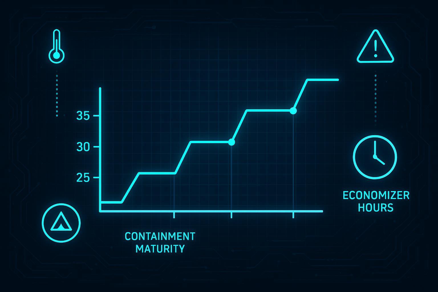
The biggest mistake teams make when “raising setpoints” is treating it like a single change request.
A safer pattern is to raise setpoints in phases, with monitoring and airflow maturity increasing alongside the setpoint.
Phased setpoint raise
A phased approach typically looks like:
Baseline: validate inlet measurements and identify local hot spots.
Containment + sealing: reduce mixing and improve predictability.
Raise supply setpoint in small steps, hold each step long enough to observe.
Lock in alarms and response playbooks.
If your facility is pursuing an economizer-first sequence, Coolnetpower’s guide on how to cut data center PUE under 1.2 with free cooling provides a practical staging mindset: improve airflow control and instrumentation first, then harvest efficiency.
Containment tactics
Containment isn’t just an efficiency project—it’s an envelope control project.
Tactics that tend to pay off quickly:
Close open U-space with blanking panels.
Seal cable cutouts and obvious leakage points.
Standardize cold-aisle containment details so commissioning can be repeated row-to-row.
Treat door states (open/closed) as operational variables; if doors are routinely open, your control model should assume that reality.
Economizer strategy
Economizers can be powerful, but only if your envelope discipline is strong.
Three practical controls points for 2026 designs:
Control to inlet conditions, not return air averages.
Use dew point as a first-class alarm to prevent condensation risk.
Pair higher setpoints with filtration and contamination monitoring so corrosion risk doesn’t become your hidden “energy tax.”
AI/H1 and liquid cooling
As rack densities rise, the control problem changes: your challenge is less “how do I cool the room?” and more “how do I keep inlets and cold plates within envelope during fast, spiky loads?”
Density thresholds
A useful decision lens is to pick the heat-capture point that matches density:
Lower densities often remain air-dominant (with better airflow control and containment).
Mid densities often benefit from capturing heat at the rack (rear-door HX) to stabilize inlets.
Higher densities often require direct liquid heat capture at the chip (direct-to-chip), with residual air cooling for remaining components.
For a practical hybrid roadmap, see Coolnetpower’s educational guide on hybrid air–liquid retrofit strategy with RDHx and direct-to-chip. It’s a useful reference for teams that want to stay standards-aligned without locking into a single technology too early.
Where Coolnetpower fits (kept intentionally non-promotional): in real projects, operators often need a coherent package across precision cooling, controls/monitoring integration, and liquid cooling components so that setpoints and envelopes can be held consistently across normal operation and excursions. Treat vendor selection as a reliability exercise: ask for inlet control performance at your specified conditions, alarm/telemetry integration expectations, and maintenance/commissioning checklists.
Warm-water operation
Warm-water operation can expand heat rejection options (including dry coolers and more economizer hours), but it shifts the risk focus:
Condensation risk management becomes central.
Dew point monitoring needs to be tighter and closer to the control points that can create cold surfaces.
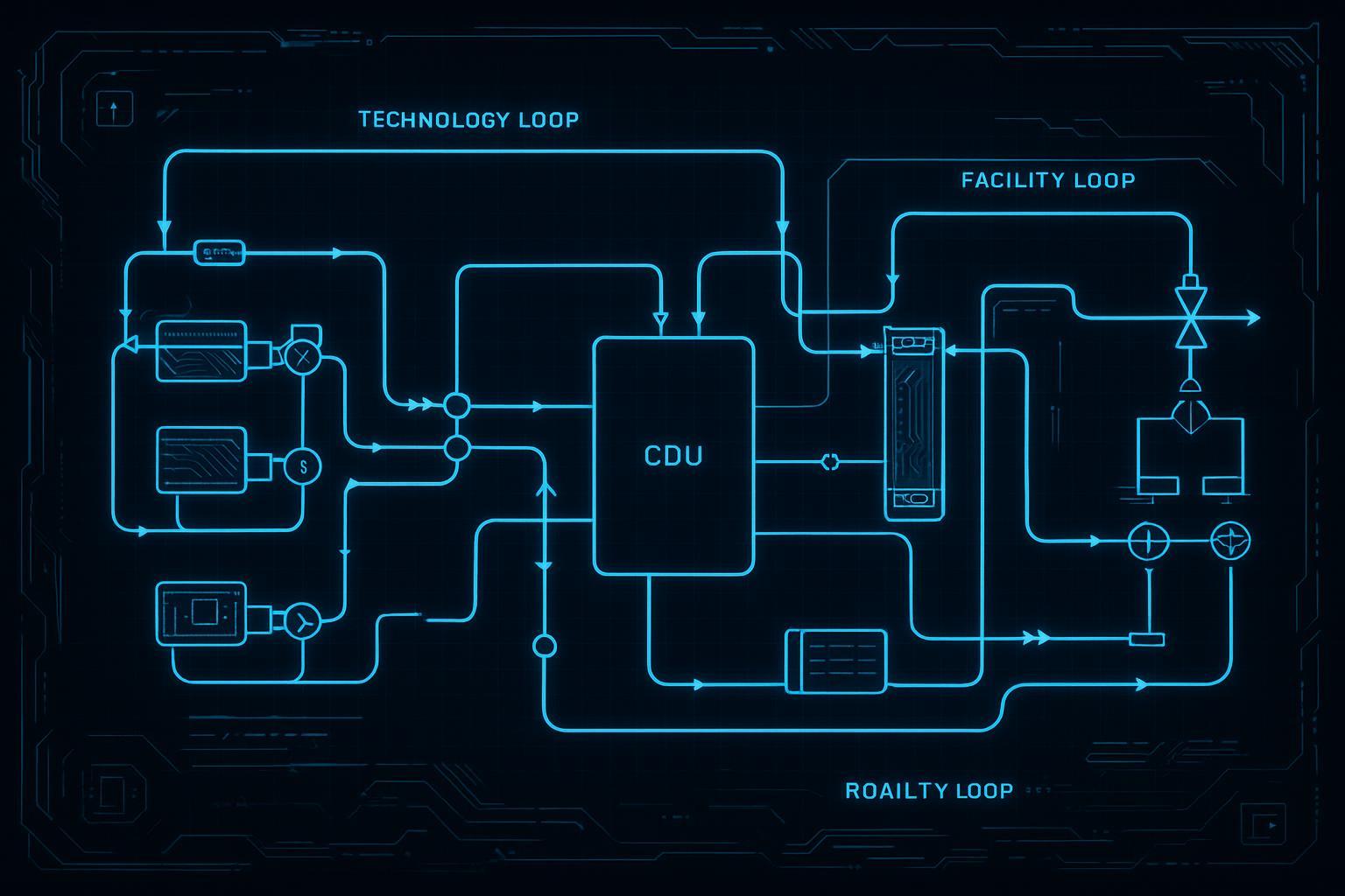
As a practical rule, keep facility water temperatures safely above room dew point to avoid condensation on coils, piping, and quick connects. If your team is designing retrofit loops, it’s worth reviewing the split between facility and technology loops and the role of the CDU as a boundary device (Coolnetpower’s primer on CDU essentials for stable liquid loops is a helpful overview).
Reliability and PUE
Efficiency improvements that increase operational risk are rarely “free.” The goal is a reliability-neutral path to PUE gains.
A reliability-forward approach looks like:
Use recommended envelopes as your default steady-state targets.
Allow excursions only with evidence (monitoring, trend history, and response playbooks).
Treat filtration and corrosion monitoring as part of the efficiency program, not a separate initiative.
Pro Tip: When you raise setpoints, validate not only steady-state inlets, but also what happens during the “bad five minutes” (CRAH trip, valve transitions, door openings). That’s where most thermal incidents start.
Conclusion
In 2026, ASHRAE TC 9.9 is still most valuable as an engineering contract between IT tolerance, facility controls, and day-to-day operations.
Validate your IT class mix (A1–A4 and any H1 areas) and select setpoints accordingly.
Pair higher setpoints with containment, monitoring, and filtration—otherwise you’re trading energy savings for hidden reliability risk.
For AI/H1 racks, plan for liquid cooling and warm-water loop design early so inlets stay within envelope even during transients.
If you want a procurement-friendly next step: align internally on your target inlet envelope, then request a commissioning checklist and monitoring plan that proves you can hold it row-by-row, not just on room averages.